
Related Manuals for Yamaha HTR-5440


Summary of Contents for Yamaha HTR-5440
- Page 1 U C A HTR-5450 HTR-5440 Natural Sound AV Receiver Ampli-tuner audio-vidéo OWNER’S MANUAL MODE D’EMPLOI...
-
Page 2: Safety Instructions
CAUTION RISK OF ELECTRIC SHOCK DO NOT OPEN CAUTION: TO REDUCE THE RISK OF ELECTRIC SHOCK, DO NOT REMOVE COVER (OR BACK). NO USER-SERVICEABLE PARTS INSIDE. REFER SERVICING TO QUALIFIED SERVICE PERSONNEL. • Explanation of Graphical Symbols The lightning flash with arrowhead symbol, within an equilateral triangle, is intended to alert you to the presence of uninsulated “dangerous voltage”... - Page 3 This product, when installed as indicated in the instructions contained in this manual, meets FCC requirements. Modifications not expressly approved by Yamaha may void your authority, granted by the FCC, to use the product. IMPORTANT : When connecting this product to accessories and/or another product use only high quality shielded cables.
- Page 4 Using this unit with a higher voltage than specified is dangerous and may cause fire, damage to this unit, and/or personal injury. YAMAHA will not be held responsible for any damage resulting from use of this unit with a voltage other than specified.
-
Page 5: Table Of Contents
Returning to the Factory Setting ... 46 SOUND FIELD PROGRAM ... 47 Hi-Fi DSP Programs ... 47 CINEMA DSP Programs ... 47 APPENDIX TROUBLESHOOTING ... 50 SPECIFICATIONS (HTR-5450) ... 54 SPECIFICATIONS (HTR-5440) ... 55 GLOSSARY ... 56 INDEX ... 58... -
Page 6: Features
95 W + 95 W (8 Ω) Rear: • This document is the Owner’s Manual for both the HTR-5450 and HTR-5440. For details on various functions unique to each model, see the descriptions given for each model name. Illustrations for the HTR-5450 are used for common functions. -
Page 7: Getting Started
Checking the Package Contents Check that the following items are included in your package. Remote control Battery Installation in the Remote Control Turn the remote control over and slide the battery compartment cover in the direction of the arrow. Insert the batteries (AAA, R03 or UM-4 type) according to the polarity markings on the inside of the battery compartment. -
Page 8: Controls And Functions
Front Panel HTR-5450 D I G I T A L SURROUND STANDBY BASS TREBLE BALANCE SPEAKERS – – HTR-5440 D I G I T A L SURROUND STANDBY BASS TREBLE BALANCE SPEAKERS – – STANDBY/ON Press this switch to turn on the power of this unit or to set this unit in the standby mode. - Page 9 VOLUME Turn this control to turn up or down the volume. 6CH INPUT Press this button to select the source connected to the 6CH INPUT jacks. The source selected by pressing 6CH INPUT takes priority over the source selected with INPUT l / h (or the input selector buttons on the remote control).
-
Page 10: Remote Control
CONTROLS AND FUNCTIONS Remote Control This section describes basic operation of this unit with the remote control. First, press AMP(TUNER) on the component selector. Refer to “PRESET REMOTE CONTROL” for full details. Indicator This flashes in red when pressing a button on the remote control. -
Page 11: Using The Remote Control
EFFECT Press this button to turn on or off the effect speakers (center and rear). PRG+, PRG– Press these buttons to select a DSP program. Once you press SET MENU, these buttons are used for selecting the SET MENU item. SET MENU Press this button to select the items in the SET MENU. -
Page 12: Display
CONTROLS AND FUNCTIONS Display VIRTUAL DOLBY DTS DIGITAL DIGITAL PRO LOGIC ENHANCED PRO LOGIC t indicator The “t” indicator lights up when the built-in DTS decoder is turned on. VIRTUAL indicator This lights up when using Virtual CINEMA DSP. g and o indicators “... -
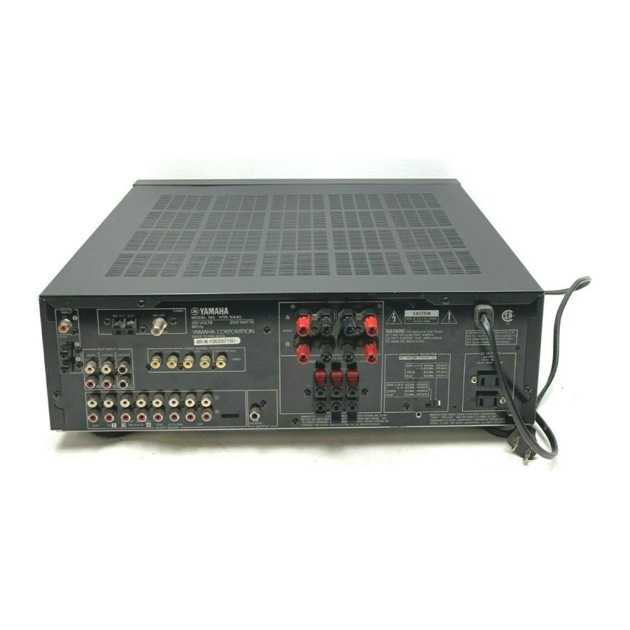
Page 13: Rear Panel
DIGITAL D-TV/CBL VCR 1 OUTPUT AUDIO SIGNAL As this terminal is used for an examination in the factory, do not connect any equipment to this terminal. HTR-5440 DIGITAL INPUT TUNER AM ANT GND FM ANT COAXIAL 75 UNBAL. OPTICAL D-TV/CBL... -
Page 14: Preparation
LFE (low frequency effect) channel with high fidelity when playing back a source encoded with Dolby Digital or DTS. The YAMAHA Active Servo Processing Subwoofer System is ideal for natural and lively bass reproduction. -
Page 15: Connections
When you connect other YAMAHA audio components (such as a tape deck, MD recorder and CD player or changer), connect it to the jacks with the same number labels as !, #, $ etc. -
Page 16: Connecting Audio Components
HTR-5450 only • All digital input jacks are acceptable for 96-kHz sampling digital signals. HTR-5440 only • When making connections between the digital signal jacks, you should connect the components to the same-named analog audio signal jacks of this unit, because a digital signal cannot be recorded by a recording component connected to this unit. - Page 17 OUTPUT CD player COAXIAL OUTPUT DIGITAL INPUT COAXIAL OPTICAL D-TV/CBL MD/CD-R OPTICAL MD/CD-R DIGITAL (HTR-5450/U.S.A. model) OUTPUT OUTPUT Audio component indicates signal direction indicates left analog cables indicates right analog cables indicates optical cables indicates coaxial cables MAIN OUTPUT TUNER AM ANT GND FM ANT 75 UNBAL.
-
Page 18: Connecting Video Components
• If video signals are input from both the S VIDEO input and composite input jacks, the signals will be directed to their respective output jacks. VIDEO S VIDEO S Video signal Signal flow HTR-5440 VIDEO Game console or camcorder L AUDIO R VIDEO AUX AUDIO OUT R... - Page 19 OPTICAL OUTPUT DVD player AUDIO S VIDEO OUTPUT OUTPUT DIGITAL INPUT COAXIAL OPTICAL D-TV/CBL MAIN MD/CD-R OPTICAL MD/CD-R DIGITAL OUTPUT S VIDEO OUTPUT OUTPUT TV/digital TV OPTICAL or cable OUTPUT TV/satellite tuner indicates signal direction indicates left analog cables indicates right analog cables indicates optical cables indicates video cables indicates S-video cables...
-
Page 20: Connecting Speakers
CONNECTIONS Connecting Speakers Be sure to connect the right channel (R), left channel (L), “+” (red) and “–” (black) properly. If the connections are faulty, no sound will be heard from the speakers, and if the polarity of the speaker connections is incorrect, the sound will be unnatural and lack bass. -
Page 21: Subwoofer Connection
I Subwoofer connection When using a subwoofer with built-in amplifier, including the YAMAHA Active Servo Processing Subwoofer System, connect the input jack of the subwoofer system to this jack. Low bass signals distributed from the main, center and/or rear channels are directed to this jack. (The cut-off frequency of this jack is 90 Hz.) The LFE (low-frequency... -
Page 22: Impedance Selector Switch
CONNECTIONS IMPEDANCE SELECTOR Switch WARNING Do not change the IMPEDANCE SELECTOR switch setting while the power to this unit is on, otherwise the unit may be damaged. If this unit fails to turn on when STANDBY/ON (or POWER) is pressed, the IMPEDANCE SELECTOR switch may not be fully slid either position. -
Page 23: Adjusting The Speaker Balance
ADJUSTING THE SPEAKER BALANCE This procedure lets you adjust the sound output level balance between the main, center and rear speakers by using the built-in test tone generator. When this adjustment is performed, the sound output level heard at the listening position will be the same from each speaker. - Page 24 ADJUSTING THE SPEAKER BALANCE Adjust BALANCE on the front panel so that the sound output level of the right main speaker and the left main speaker is the same. Press –/+ repeatedly to adjust the output level of the speaker currently outputting the test tone so that it becomes almost the same as that of the main...
-
Page 25: Basic Operation
BASIC OPERATION When using the remote control, press AMP(TUNER) on the component selector. D I G I T A L D I G I T A L STANDBY SURROUND BASS TREBLE BALANCE SPEAKERS PROGRAM EFFECT – – PHONES S VIDEO VIDEO L AUDIO R SILENT... -
Page 26: Background Video Function
PLAYING A SOURCE Play the source. Refer to the instructions for the source component (and “TUNING” for details). Note • When controlling an audio/video component (MD recorder, CD player, DVD player, tape deck, etc.) with the remote control, press one of the component selector buttons, (TAPE/MD, CD, DVD/ LD, etc.), which corresponds to the component you want to control. -
Page 27: Input Modes And Indications
Input Modes and Indications When using the remote control, press AMP(TUNER) on the component selector. This unit comes with various input jacks. If your component is connected to more than one type of input jack, you can set the priority of the input signal. Press INPUT MODE (or the input selector button that you have pressed to select the input source on the remote control) repeatedly... -
Page 28: Selecting A Dsp Program
PLAYING A SOURCE Selecting a DSP Program You can enhance your listening experience by selecting a DSP program. Refer to “SOUND FIELD PROGRAM” for details about each program. • Make sure that the sound effect is turned on (see page 25). I On the remote control Press AMP(TUNER) on the component selector. -
Page 29: Canceling The Sound Effect (Turning Off The Effect Speakers)
Virtual CINEMA DSP Virtual CINEMA DSP allows you to enjoy the sound field effects of the DSP program without rear speakers. Using YAMAHA original technology, natural surround reproduction is possible through the generation of a virtual speaker. The sound field processing is changed to the Virtual CINEMA DSP mode by setting “REAR LR SP”... -
Page 30: Tuning
AM antenna is connected to this unit. A properly installed outdoor antenna provides clearer reception than an indoor one. If you experience poor reception quality, an outdoor antenna may improve the quality. Consult the nearest authorized YAMAHA dealer or service center about the outdoor antennas. -
Page 31: Automatic Tuning
Automatic Tuning Automatic tuning is effective when station signals are strong and there is no interference. D I G I T A L D I G I T A L SURROUND STANDBY BASS TREBLE BALANCE SPEAKERS PROGRAM EFFECT PRESET/TUNING – –... -
Page 32: Automatic Preset Tuning (For Fm Stations Only)
TUNING Automatic Preset Tuning (for FM stations only) You can make use of the automatic preset tuning function for FM stations only. This function enables the unit to automatically tune in with strong signals and to sequentially store up to 40 FM stations (5 groups x 8 stations). D I G I T A L D I G I T A L SURROUND... -
Page 33: Manual Preset Tuning
Manual Preset Tuning You can also store up to 40 stations (5 groups x 8 stations) manually. D I G I T A L D I G I T A L STANDBY SURROUND BASS TREBLE BALANCE SPEAKERS PROGRAM EFFECT PRESET/TUNING –... -
Page 34: Exchanging Preset Stations
TUNING Exchanging Preset Stations You can exchange the assignment of two preset stations with each other. Example: Exchange preset station “E1” with “A5” D I G I T A L D I G I T A L SURROUND STANDBY BASS TREBLE BALANCE SPEAKERS... -
Page 35: Recording A Source
Recording adjustments and other operations are performed from the recording component. Refer to the instructions for these components. D I G I T A L D I G I T A L STANDBY SURROUND BASS TREBLE BALANCE SPEAKERS PROGRAM EFFECT PRESET/TUNING –... -
Page 36: Advanced Operation
ADVANCED OPERATION The SET MENU consists of 9 items including the speaker mode setting. Use the SET MENU to enjoy the optimum audio/video playback for your system. • You can adjust the items on the SET MENU while playing a source. -
Page 37: Speaker Set (Speaker Mode Settings)
Memory back-up The memory back-up circuit prevents the stored data from being lost even if this unit is set in the standby mode, the power cord is disconnected from the AC outlet, or the power supply is temporarily cut due to power failure. -
Page 38: Hp Tone Ctrl (Headphone Tone Control)
SET MENU I BASS OUT (bass out mode) LFE signals carry low-frequency effects when this unit decodes a Dolby Digital or DTS signal. Low-frequency signals are defined as 90 Hz and below. Choices: SWFR (subwoofer), MAIN, BOTH Initial setting: BOTH SWFR Select this if you use a subwoofer. -
Page 39: Input Mode (Initial Input Mode)
Initial setting: (5) CD Note • You cannot select an item more than once for the same type of jack. HTR-5440 I 3A (1) and (2) (for the OPTICAL INPUT jacks) Initial settings: (1) DVD (2) D-TV/CBL I 3B (3) (for the COAXIAL INPUT... -
Page 40: Dts Set (Dts Lfe Level)
SET MENU 6 DTS SET (DTS LFE level) This setting is effective only when this unit decodes DTS signals. Use this feature to adjust the output level of the LFE (low- frequency effect) channel when playing back a DTS signal. The LFE signal carries the low-frequency special effect sound which is only added to certain scenes. -
Page 41: Delay Time And Speaker Output Levels
DELAY TIME AND SPEAKER OUTPUT LEVELS When using the digital sound field processor with the Dolby Pro Logic decoder, Dolby Digital decoder or DTS decoder, you can adjust the delay time between the main sound and sound effect, and each speaker’s output level as you wish. Delay Time You can adjust the time difference between the beginning of the sound from the main speakers and the beginning of the... -
Page 42: Adjusting Method
DELAY TIME AND SPEAKER OUTPUT LEVELS Adjusting Method Adjustments should be performed with the remote control while watching the information on the display. Press AMP(TUNER) on the component selector. Press TIME/LEVEL repeatedly to select the item you want to adjust. Each time you press TIME/LEVEL, the selected item changes and appears on the display as below. -
Page 43: Sleep Timer
The SLEEP timer can be used to automatically set this unit in the standby mode. This timer is useful when you are going to sleep while enjoying a broadcast or other desired input source. The SLEEP timer can only be set with the remote control. -
Page 44: Preset Remote Control
• The button functions on the remote control differ depending on the operation mode. Refer to the following pages for details. • When shipped from the factory, the YAMAHA manufacturer codes listed on page 49 are set for each dial position. If unable to operate your YAMAHA A/V component, please try using another YAMAHA code. -
Page 45: Description Of Each Mode
POWER This button turns this unit on if you have set the code for a YAMAHA tape deck, MD recorder or CD recorder. This button turns on the tape deck, MD recorder or CD recorder that has a remote control with a power button if you have set the code. -
Page 46: Cd Mode
POWER This button turns this unit on if you have set the code for a YAMAHA CD player. This button turns on the CD player that has a remote control with a power button if you have set the code. -
Page 47: Dvd/Ld Mode
Press DVD/LD. POWER This button turns this unit on if you have set the code for a YAMAHA DVD or LD player. This button turns on the DVD or LD player that has a remote control with a power button if you have set the code. -
Page 48: Vcr Mode
PRESET REMOTE CONTROL I VCR MODE Note • TV VOLUME, TV INPUT and TV SLEEP function if you have set the code for your TV. VCR POWER VCR CHANNEL –/+ VOLUME MUTE TV SLEEP VCR REC Press this button twice to start recording. -
Page 49: Setting The Manufacturer Code
Setting the Manufacturer Code You can set the code for the manufacturer of your component after pressing the component selector buttons other than AMP(TUNER). Turn on your component to be used. Press one of the component selector buttons which corresponds to the component to be controlled. -
Page 50: Returning To The Factory Setting
The indicator flashes twice. Enter the code number “0000”. Make sure that the indicator flashes twice. Code Set component 0101 0006 0002 0008 (YAMAHA DVD player) 0005 (YAMAHA CD player) 0024 (YAMAHA MD recorder) Set code... -
Page 51: Sound Field Program
A digital sound field processor (DSP) based on the latest YAMAHA technology is built into this unit. It is possible to play back various sound fields for the source you are listening to. Note • Regardless of the program name and characteristics listed in the table below, select the sound field program that sounds best to you. - Page 52 SOUND FIELD PROGRAM I For movie programs: Nos. 7 to 9 Program (group) MOVIE THEATER 1 SPECTACLE SCI-FI MOVIE THEATER 2 ADVENTURE 70 mm GENERAL NORMAL q/DTS SURROUND ENHANCED Notes • The “ x ” indicator does not light up when selecting the sub-program “NORMAL” of the q/DTS SURROUND program. •...
- Page 53 70 mm SCI-FI 70 mm ADVENTURE 70 mm GENERAL These programs use YAMAHA’s tri-field DSP processing on each of the Dolby Digital or DTS signals for the front, left surround and right surround channels. This processing enables this unit to reproduce the immense sound field and surround expression of a Dolby Digital- or DTS-equipped movie theater without sacrificing the clear separation of all channels.
-
Page 54: Appendix
Refer to the chart below when the unit does not function properly. If the problem you are experiencing is not listed below or if the instruction below does not help, set this unit in the standby mode, disconnect the power cord and contact the nearest authorized YAMAHA dealer or service center. I General... - Page 55 Problem No sound from the effect The sound effect is off. speakers. A Dolby Surround, Dolby Digital or DTS decoding DSP program is being used with material not encoded with Dolby Surround, Dolby Digital or DTS. A 96-kHz sampling digital signal is being input to this unit.
- Page 56 TROUBLESHOOTING Problem The volume level cannot The component connected to the REC OUT jacks of this unit is turned off. be increased, or the sound is distorted. The effect and surround It is not possible to record the effect and sounds cannot be surround sounds by a recording component.
- Page 57 I Tuner Problem FM stereo reception The characteristics of FM stereo broadcasts may cause this problem when the transmitter is is noisy. too far away or the antenna input is poor. There is distortion, There is multipath interference. and clear reception cannot be obtained even with a good FM antenna.
-
Page 58: Specifications (Htr-5450)
AUDIO SECTION • Minimum RMS Output Power for Main, Center, Rear 20 Hz to 20 kHz, 0.06% THD, 8 ohms [U.S.A. and Canada models] ... 80 W [Singapore, China and General models] ... 70 W • Maximum power 1 kHz, 0.7% THD, 8 ohms ... 100 W •... -
Page 59: Specifications (Htr-5440)
• Signal to Noise Ratio ... 50 dB or more • Frequency Response (MONITOR OUT) Composite ... 5 Hz to 10 MHz, –3 dB SPECIFICATIONS (HTR-5440) FM SECTION • Tuning Range [U.S.A. and Canada models] ... 87.5 to 107.9 MHz [Europe, U.K., Australia, Singapore, China and... -
Page 60: Glossary
DTS systems to provide the visual and audio experience of movie theater in the listening room of your own home. I SILENT CINEMA YAMAHA has developed a natural, realistic sound effect DSP algorithm for headphones. Parameters for headphones have been set for each sound field so that accurate representations of all the sound field programs can be enjoyed on headphones. -
Page 61: I/O Assign (Set Menu)
GLOSSARY I S VIDEO signal HTR-5450 only With S VIDEO signal system, the video signal normally transmitted using a pin cable is separated and transmitted as the Y signal for the luminance and the C signal for the chrominance through the S VIDEO cable. Using the S VIDEO jack eliminates video signal transmission loss and allows recording and playback of even more beautiful images. -
Page 62: Index
AC outlets ... 18 Antennas ... 26 BALANCE ... 22 BGV function ... 22 CBL/SAT mode ... 44 CD mode ... 42 CINEMA DSP ... 47, 56 Connections Antennas ... 26 Audio components (MD recorder, CD recorder and CD player) ... 12 External decoder ... - Page 63 LIST OF MANUFACTURER’S CODES LISTES DES CODES FABRICANT Elin Elta A-Mark 1161 Emerson A Tandy 0941 Abex 1151 Admira 1141 Adventura 1131 Aiko 1121 Akai 0331, 1101, 1111 Alba 0431 Alleron 1091 Envision Ambassador 1081 Erres Amstrad 0481, 1081 Etron Anam 0251, 1041, 1051, Ferguson...
- Page 64 0971, 0991, 1031, Signal 1091, 1111, 1771 SL Marx Watson 1001 Spectavision Xogego 1611, 1621, 1661, Standard Components 0186 1741, 1761 Starcom V Yamaha 0361, 1031, 1111 Stargate Yoko 1001 Sylvania/Texscan Zenith 0011, 0041, 0891, Teknika 0991, 1771 Teleservice Zonda...
- Page 65 Sharp Realistic 0402, 0472, 0612, Sony 0682, 0842, 0902, Technics 0912, 0922, 0932, Thomson 0992 Toshiba Ricoh 0352, 0362 Yamaha Saisho 0212, 0582, 0722, 0732, 0742, 0772 Zenith Salora 0612, 0762 LD PLAYER Samsung 0212, 0312, 0922, 0962 Aiwa Sanky...
- Page 66 YAMAHA ELECTRONIQUE FRANCE S.A. RUE AMBROISE CROIZAT BP70 CROISSY-BEAUBOURG 77312 MARNE-LA-VALLEE CEDEX02, FRANCE YAMAHA ELECTRONICS (UK) LTD. YAMAHA HOUSE, 200 RICKMANSWORTH ROAD WATFORD, HERTS WD1 7JS, ENGLAND YAMAHA SCANDINAVIA A.B. J A WETTERGRENS GATA 1, BOX 30053, 400 43 VÄSTRA FRÖLUNDA, SWEDEN Printed in Malaysia ID V723100-2 YAMAHA MUSIC AUSTRALIA PTY, LTD.
- Page 67 Connection Guide (when listening to a digital 5.1-channel source) DVD player AUDIO OUT S VIDEO VIDEO OPTICAL S VIDEO OPTICAL AUDIO VIDEO DIGITAL INPUT TUNER AM ANT GND FM ANT COAXIAL 75 UNBAL. OPTICAL D-TV/CBL 6CH INPUT VIDEO SIGNAL D-TV/CBL IN VCR 1 OUT MAIN SURROUND...
- Page 68 Quick Reference Card AMP(TUNER) POWER POWER Input selector buttons 6CH INPUT A/B/C/D/E EFFECT TEST PRESET–/+ VOLUME VOLUME TV VOLUME MUTE SLEEP SLEEP TV INPUT REC/PAUSE –/+ PRG+, DIR A (TAPE) PRG– SKIP– (MD) TIME/LEVEL REWIND (TAPE) SEARCH (MD) MENU TAPE/MD POWER Input selector buttons...
- Page 69 Quick Reference Card DVD MENU POWER Numeric buttons CLEAR CHANNEL–/+ DISC SKIP–/+ VOLUME TV VOLUME MUTE RETURN INDEX TV INPUT MENU UP MENU SELECT MENU LEFT MENU RIGHT TITLE MENU MENU DOWN Press this button twice to start recording. Appuyer deux fois sur cette touche pour commencer l’enregistrement. Drücken Sie diese Taste zweimal, um die Aufnahme zu starten.