Table of Contents
Advertisement
Quick Links
Advertisement
Table of Contents

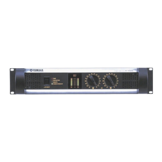
Summary of Contents for Yamaha PC4800N
- Page 1 POWER AMPLIFIER Owner’s Manual...
-
Page 2: Explanation Of Graphical Symbols
300 ohm ribbon lead, change the lead-in to coaxial type cable. If these corrective measures do not produce satisfactory results, please contact the local retailer authorized to distribute this type of product. If you can not locate the appropriate retailer, please contact Yamaha Corporation of America, Electronic Service Division, 6600 Orangethorpe Ave, Buena Park, CA 90620 The above statements apply ONLY to those products distributed by Yamaha Corporation of America or its subsidiaries. - Page 3 Precautions WARNING Installation • Connect this unit’s power cord only to an AC outlet of the type stated in this Owner’s Manual or as marked on the unit. Failure to do so is a fire and electrical shock hazard. • Do not allow water to enter this unit or allow the unit to become wet.
- Page 4 CAUTION Installation • Keep this unit away from the following locations: - Locations exposed to oil splashes or steam, such as near cooking stoves, humidifiers, etc. - Unstable surfaces, such as a wobbly table or slope. - Locations exposed to excessive heat, such as inside a car with all the windows closed, or places that receive direct sunlight.
-
Page 5: Table Of Contents
• Variable-speed, low-noise cooling fan system ensures high reliability even under the most demanding conditions. This Owner’s Manual applies to the PC9500N and PC4800N power amplifier. In order to take full advantage of your power amplifier and enjoy long and trouble-free operation, please read this Owner’s Manual carefully before using your Power Amplifier. -
Page 6: Controls And Functions
Controls and Functions Front Panel 2 3 4 POWER/STAND-BY switch and indicator This turns the power of the amplifier on/off. When you press the switch to turn on the power, the indica- tor will light green. If the amplifier is connected to an external control unit and the amplifier has been commanded to enter STAND-BY mode, this indicator will light orange. -
Page 7: Rear Panel
Rear Panel XLR inputs These balanced XLR-3-31 type connectors are used to connect input signals. They are wired pin 1–ground, pin 2–hot (+), and pin 3–cold (–). In Bridge mode, only the XLR input of the channel A is active. MODE switch •... -
Page 8: Speaker Connections
Speaker connections Speakers can be connected to this amplifier in the following two ways. The speaker impedance will depend on the connection method and on the number of speakers that are connected. Refer to the following diagrams, and make sure that the speaker impedance is not less than the value prescribed for each type of connection. -
Page 9: Connection
Connection Using a Euroblock connector 1. If the wire insertion ports are closed, turn the screws on top of the connector counterclockwise to open the ports. 2. Insert the wires into the appropriate ports, following the indication of the pole on the input terminal, turn the screws on top of the connector clockwise to fix the wires. -
Page 10: Air Flow
The figure on the left below shows an example of a fan kit (panels and two fans) on the top slot of the rack. The fans are Minebia 3115PS-12T-B30 (with 0.9 m The figure on the right below is a dimensional diagram of a panel on which two 3115PS-12T-B30 are installed. Fan kit PC9500N/ PC4800N PC9500N/ PC4800N Air exhaust O or more maximum static pressure. -
Page 11: Specifications
Specifications subject to change without notice. For European Model Purchaser/User information specified in EN55103-1 and EN55103-2. Inrush Current: 20A (PC9500N) / 25A (PC4800N) Conformed Environment: E1, E2, E3 and E4. PC9500N 120 V (US)/ 240 V (A) 230 V (EU) -
Page 12: Block Diagram
Block Diagram... -
Page 13: Dimensions
Dimensions 25 30 30 25 Unit: mm... -
Page 14: Troubleshooting
Use a speaker with a minimum impedance of 4 (8 in Bridge mode). Check the ventilation around the amplifier and improve the airflow if necessary. Consult your dealer or a Yamaha service center. Mode:STEREO Both ch Power Consumption[W] Output Power[W] 1000 10000 Mode:STEREO... - Page 16 YAMAHA CORPORATION Pro Audio & Digital Musical Instrument Division V853450 R11 AP 16 P.O. Box 3, Hamamatsu, 430-8651, Japan NP Printed in Taiwan...


