Advertisement
Advertisement
Table of Contents

Related Manuals for Yamaha P-2200/2201


Summary of Contents for Yamaha P-2200/2201
- Page 1 YAMAHA AUTHORIZED PRODUCT MANUAL P-2200/2201 SYSTEM AMPLIFIER...
- Page 2 P-2200/2201 OPERATING MANUAL...
-
Page 3: About This Manual
The P-2200 is a system oriented amplifier, made to be used in conjunction with mixers, consoles, frequency dividing networks and speakers — those made by Yamaha or by other manufacturers. Like any power amplifier, the P-2200's performance depends on system design and installation, in addition to its own capabilities. - Page 4 THE P-2200/2201 BRIEF OPERATING INSTRUCTIONS INTRODUCTION GENERAL SPECIFICATIONS PERFORMANCE GRAPHS & A DISCUSSION OF SPECIFICATIONS THE DISTINCTION BETWEEN PROFESSIONAL AND HI-FI EQUIPMENT IMPEDANCE OPERATING LEVELS DYNAMIC RANGE GAIN OVERLAP AND HEADROOM INPUT SENSITIVITY RATINGS PROFESSIONAL EQUIPMENT ADVANTAGES INSTALLATION AND DETAILED OPERATION...
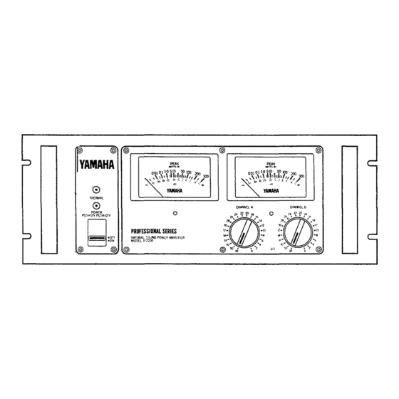
- Page 5 THE P-2200/2201 BRIEF OPERATING INSTRUCTIONS Fig. 1A - P-2200 Front Panel Fig. 1B - P2201 Front Panel A. Input Attenuators Calibrated, stepped input attenuators lower input signal levels ahead of amplification stages. B. Peak Reading Meters (P-2200 only) Meters display instantaneous (peak) power output into an 8-ohm load over a full 50dB range;...
- Page 6 2.5 ohms. D. AC Power Cord For the U.S. and Canadian models, the P-2200/2201 require 117 VAC 50 or 60 Hz line ( 1 0 5 V min., 1 3 5 V max.; 8 amps max. at 120 volts).
- Page 7 INTRODUCTION The P-2200 is not just "another big amplifier;" it is an exciting new approach to high power sound. Yamaha's leadership is clearly demonstrated by the P-2200's pro- fessional features, sophisticated design, and uncom- promising performance. PEAK READING METERS* Instead of the more common and slow responding...
-
Page 8: General Specifications
GENERAL SPECIFICATIONS Power Output Per Channel: (Refer to Figure 3. Ambient room temperature for tests: 25-degrees Centigrade.) 200 Watts continuous average sine wave power into 8 ohms with less than 0.05% THD, (Total Harmonic Distortion), over a bandwidth of 20Hz to 20kHz, both channels driven. - Page 9 Controls: 22-position, log-linear, detented, and dB-calibrated INPUT ATTENUATORS (one per channel) attenuate input signal in 2dB steps from 0dB attenuation to -34dB, then steps of -37dB, -42dB, -50dB, infinity; Power (ON-OFF) switch; INPUT POLARITY switches. Fuses: AGC (3AG) type, 7-amps x 2 parallel fuses for the AC line input (U.S.
- Page 10 PERFORMANCE GRAPHS & A DISCUSSION OF SPECIFICATIONS NOTE: In the discussion beginning on Page FOUR 5, references to specific specifications assume normal stereo operation (not mono operation) unless otherwise indicated. Normal (Stereo) Graphs Fig. 3 - Power Bandwidth vs Load Impedance Fig.
- Page 11 Fig. 9 - Actual Output Impedance vs Frequency Fig. 10 - Crosstalk (Channel Separation) Fig. 1 1 - Phase Response vs Frequency Fig. 1 2 - Power Consumption Fig. 1 3 - Peak Program Meter Accuracy (P-2200 only)
- Page 12 Mono Mode Graphs Fig. 14 - Power Bandwidth vs Frequency (Mono Mode) at 16 Load Impedance Fig. 16 - Frequency Response (Mono Mode) at 16 Impedance Fig. 1 8 - T.H.D. vs Frequency (Mono Mode) at 16 Impedance Fig. 20 - Actual Output Impedance (Mono Mode) vs Frequency Fig.
- Page 13 The following are actual oscilloscope photographs made by an independent testing laboratory. The close vertical alignment of input and output traces in Fig. 21 through 23 depicts very low phase shift, so the amplifier will not alter musical wave shapes. Fig.
-
Page 14: Power Output
POWER OUTPUT Types of Power Ratings Peak power refers to the maximum undistorted power output of an amplifier. Most amplifiers cannot sustain their peak power ratings for long periods of time without external cooling fans. Because there are many different methods of rating an amplifier's peak power, it is hard to objectively compare the peak power ratings of two amplifiers. - Page 15 Intermodulation Distortion, or I.M. is characterized by the appearance in the output waveform of fre- quencies that are equal to sums and differences of integral multiples of two or more of the frequencies present in the input signal. The difference between inter- modulation distortion and harmonic distortion is that two or more different frequencies must be present to produce intermodulation distortion (only one frequency...
- Page 16 HUM AND NOISE Hum or noise from a power amplifier disrupts a program, and is irritating to a listener. Hum and noise could be considered a form of distortion. The P-2200's hum and noise are so low that they are completely inaudible under any normal listening circumstances.
- Page 17 During the "overshoot" movement, the voice coil of the loudspeaker interacts with the loudspeaker's magnetic assembly to produce a voltage called "back E.M.F." (electro-motive force). This action is similar to the operation of a dynamic microphone. If the amplifier's output impedance is low, this "back E.M.F." voltage is shunted through the amplifier's output circuits to ground, and back to the voice coil.
- Page 18 THE DISTINCTION BETWEEN PROFESSIONAL AND HI-FI EQUIPMENT In most applications, a variety of auxiliary equipment will be connected to the P-2200, including: mixers, tape machines, compressors, graphic equalizers, echo, time delay, and reverb units, and just about any other audio electronics imaginable.
-
Page 19: Operating Levels
Thus, it is extremely important to use wide dynamic range equipment, like the P-2200 and Yamaha PM-Mixers, in a professional sound reinforcement system. In the special case of a tape recorder, where the... - Page 20 NOTE: The P-2200 actually has a maximum signal to noise ratio of 110dB (which is its dynamic range!. The SYSTEM'S Dynamic Range is limited by acoustic noise at the mic input, for the system shown, and by the maximum signal to noise ratio of the PM-700 Mixer (93dB), a very respectable figure for a high gain device.
- Page 21 6dB loss at some frequencies. A mixer with +24dB output drive, such as a Yamaha PM-Mixer, has considerably more out- put level than is needed to drive the inputs of most amplifiers so that passive devices may be used as desired.
-
Page 22: Physical Mounting
INSTALLATION AND DETAILED OPERATION PHYSICAL MOUNTING Shelf Mounting The P-2200 can be used on any surface, so long as there is adequate ventilation. Do not remove the P-2200's feet, since this would prevent air flow below the amplifier. Permanent Installation Rack Mounting Mount the P-2200 in any standard 19"... - Page 23 The low impedance pad values illustrated in Figure 38 are designed for 600-ohm lines. Commercially manu- factured pads are available; consult your Yamaha dealer. When connected between a 600-ohm or lower source and a 600-ohm or higher termination, pad attenuation values will remain fairly accurate.
- Page 24 Fig. 39A - Pads Constructed in Mini-Boxes. above +30dBm, use 1 watt, low inductance resistors. 10% tolerance is acceptable for most pads. Fig. 39B - Pad Constructed in Switchcraft Model S3FM It is possible to construct a pad within an XLR con- nector, but the extremely tight fit can adversely affect reliability.
- Page 25 TRANSFORMER AVAILABILITY The matching and step-up transformers mentioned in the preceding subsections are available from many electronic parts dealers. Yamaha does not endorse specific products by citing them herein; rather, these transformers are mentioned for convenience only. If you are unable to locate the transformers from your local electronic parts dealer, contact the manufacturer at the address shown below.
- Page 26 bridging transformer box should be used. While matching or step up transformers like those just described would maintain a balanced feed, several such boxes could over- load the source device. By using a transformer which has a high impedance primary and a high impedance secondary, the source can feed several P-2200 inputs without being overloaded.
- Page 27 20dB below the rated maximum output level for the mixer. For the Yamaha PM-180 Mixer used in the example, the maximum rated output level is +24dB (12.3 volts), so the output level should be adjusted to +4dB (1.23 volts), as indicated either on an external voltmeter, or on the mixer's VU meter (0VU).
- Page 28 use, a cable with rubberized insulation and braided shield (such as Belden #8413 or #8412) will handle easily and survive road abuse; for permanent wiring, a vinyl insulated cable with a foil shield (such as Belden #8451) is easier to strip for terminations, and it pulls through conduits with less drag.
- Page 29 The preparation of complete cables, with connectors properly installed, is the key to reliable and trouble-free operation of any sound system. For this reason, the fol- lowing illustrations are included. Experienced audio technicians may wish to review these illustrations, even if they already know how to wire connectors.
- Page 30 Solder the center conductors to their respective pins, using just enough solder to fill the end of the pins. Yamaha's wiring standard dictates that the black lead mates with pin 3 and the white (or red) with pin 2 (see footnote on page 10 of this section). Then solder the shield to pin 1 .
- Page 31 Solder the center conductors to their respective pins, using just enough solder to fill the end of the pin. Yamaha's wiring standard dictates that the black lead mates with pin 3, the white (or red) lead with 2 (see footnote on page 10 of this section). Then solder the shield to pin 1 .
- Page 32 WIRING A STANDARD PHONE PLUG (2-conductor) Parts identification. Slide shell, then insulating collar over cable end. Strip outer insulation for length equal to length of sleeve con- nection. Unwrap or unbraid shield, twist to form lead. Position outer insulation just ahead of cable clamp, strip center conductor from point just behind tip con- nection.
- Page 33 Use of the Input Polarity Switch on the P-2200 The XLR input connectors on the P-2200 are un- balanced. In one position, the switch beside the con- nectors attaches pin 2 to pin 1 (ground) leaving pin 3 "hot" (USA standard). In the other position, the switch attaches pin 3 to pin 1 (ground) leaving pin 2 "hot"...
-
Page 34: Grounding And Shielding
if higher quality transformers were used. Thus, "economy" transformers, may actually cost more in the long run than higher quality professional types. For an existing system with lower quality 70-volt transformers, a capacitor in series with the output of the P-2200 can limit the current at low frequencies (see Page SEVEN 6), and thereby avoid the possibility of constant protection circuitry operation on the P-2200, or damage to the 70-volt transformers from... - Page 35 grounding and shielding, and by the use of balanced, twisted pair cables. EMI: EMI (electro-magnetic interference) usually comes from power transformers (either in a sound system, or a building's electrical supply), motors, or cables carrying large amounts of current. EMI usually shows up in a sound system as a hum or buzz.
- Page 36 Fig. 58 - Avoiding Ground Loops in an Unbalanced System. In any audio system, there are numerous ways by which ground loops can be created. For example, if a microphone feeds two mixers through a splitter device, and the two mixers are AC grounded through their power cables, a ground loop is formed.
- Page 37 These codes are based on safety, and may vary in different localities; in all cases, local codes take precedence over any suggestions contained in this manual. Yamaha International Corporation shall not be liable for incidental or consequential damages, including injury to persons or property, resulting from improper, unsafe or illegal installation of the P-2200 or of any related equipment;...
-
Page 38: Mono Operation
Fig. 62D - 1 1 0 V AC Outlets with Lifted Neutral. Outlets will operate with voltage varying from 0 to 220V AC creating shock hazard and causing possible equipment damage. 220V AC on 1 1 0 V AC Outlet It is possible (albeit, illegal and dangerous) for a 220V AC circuit to be connected to a 1 1 0 V AC outlet as shown in Figure 62E. - Page 39 Fig. 63A - Input Splitter Transformer Setup to Operate P-2200 in "Mono" Mode. Fig. 63B - Output Connections for Operating P-2200 in "Mono" Mode. In the "mono" mode, the P-2200 will produce a full 400 watts into a 16-ohm load. The voltage output from the P-2200 in the mono mode is approximately 75 volts RMS, and since it can drive even highly reactive loads with complete stability, it is suitable for driving...
- Page 40 (high level) passive crossover. Fig. 64A - System using Conventional, Passive/High-Level Frequency Dividing Networks. Fig. 64B - Biamplified System using Yamaha F1030 Electronic Frequency Dividing Network. Headroom Program material (music or speech) is made up of many different frequencies and their harmonics.
- Page 41 Those that are built into a finished speaker system, such as Yamaha's S 4 1 1 5 H and S0112T, are exceptions. Because of the limited selection, a custom designed system with passive high level crossovers usually has to be designed around the crossover instead of around the drivers.
- Page 42 Yamaha's F1030 is a two way or three way electronic crossover which gives the designer a wide choice of crossover frequencies selectable for each of three bands by means of front panel controls.
- Page 43 EQUALIZATION, HIGH AND LOW PASS FILTERS Equalization, originally, was the process of "equalizing" the levels of the various audio frequency bands for a "flat" system response. The term now encompasses many different devices and techniques that are used for effects purposes as well as to "smooth" the response of a system.
- Page 44 +4dB (1.23 volts) line levels. The input of a hi-fi type graphic equalizer will probably require padding for use with professional type mixers such as the Yamaha PM- Mixers, and its output level may be too low to drive some common power amplifiers (the P-2200's sensitivity is high enough to allow it to be driven by most hi-fi type graphic equalizers).
-
Page 45: Speaker Protection
The following are methods of achieving some degree of protection against these abuses. Fuses Yamaha does not recommend the use of any type of fuse as speaker protection. Fuses are slow-acting devices of inconsistent quality, and do not offer adequate pro- tection for speaker systems. -
Page 46: Specific Applications
The diagram in Figure 72 shows the P-2200 used as a studio monitor amplifier. Part of the system is biampli- fied. Alternately, the Yamaha F1030 crossover could be used for a triamplified system, with another P-2200 or a smaller amplifier, such as the P-2100, for the super tweeter. - Page 47 Concert Sound Figure 73 illustrates the P-2200 in a typical setup for concert reinforcement. Note that there are a number of completely separate feeds, with separate limiters, equalizers, electronic crossovers, and power amplifiers. The P-2200's peak reading meters are a special advantage in concert sound systems.
- Page 48 Portable Instrument Amplifier Figure 74 details possible connections for a portable setup for an electric bass. Ideal for this application, the P-2200 can easily reproduce the high power bass notes that may be clipped off by lower power instrument amplifiers. Thus, it will "clean up" a bass sound, and, because clipping is dangerous to speaker systems, the P-2200's high power output may be easier on a speaker system than a low power amplifier.
- Page 49 Discotheque Disco systems, such as the one diagrammed in Figure 75, really test an amplifier's endurance. The music from a record album may be highly compressed so that its average power content is high, and the amplifier may not get even a short rest during many hours of operation each night.
- Page 50 Commercial Sound Systems Figure 76 diagrams a theatre reinforcement system from the viewpoint of its power amplifier. Note the time delay device that feeds the P-2200 for the under- balcony distributed speakers. This P-2200 is connected for "mono" 70-volt operation; the main P-2200 is connected for biamplified operation.
- Page 51 The factory paging/background music system in Figure 77 also shows the P-2200 used in "mono" 70-volt mode. One P-2200 feeds the main factory areas with a highly compressed signal. The other P-2200 feeds office areas with a separate, less compressed signal that has been equalized for a more natural sound.
- Page 52 A decrease of 20dB is equivalent to 1 / 1 0 the voltage or SPL. SPECIAL USE OF dB (volts) IN THIS MANUAL Assume that a Yamaha PM-Mixer has a constant input voltage, such as the sinewave signal from a test Answer:+20dBV generator.
-
Page 53: Ohm's Law
be valid only at a single load impedance, usually 600 or 150 ohms. It's common to rate a mixer's maximum output in dBm referenced to 600-ohms, and to treat this rating as if it were a voltage rating, even though it is actually a power rating. - Page 54 The Voltage across the Resistor is Less Than the Source Voltage due to the voltage drop across the output resistor R NOTE: X is the output resistance (or impedance) of the source. Y is the voltage drop across the output resistance which varies depending on other circuit parameters.
- Page 55 Fig. 81 - Series and Parallel Impedances. VOLTAGE AND CURRENT DIVISION When two or more impedances are connected in series across a voltage source they share the voltage among themselves according to the following formulas, where N is the number of impedances: (see Figure 82) For two impedances: For any number (N) of impedances: If the ohmic value of all the impedances is the same,...
- Page 56 (audio common). A FLOATING circuit has no ground reference, as illustrated by the Yamaha PM-180, PM-430 and PM-700 Mixers' Channel Inputs and XLR outputs. A BALANCED circuit requires either a center tapped transformer, or resistors from each side of the transfor- mer to ground;...
-
Page 57: Other Considerations
NOTES: "N " is the number of turns on the primary side of the transformer, " N " is the number of turns on the secondary side of the transformer. "V " is the voltage level on the primary side of the transformer, "... - Page 58 YAMAHA SINCE 1887...
- Page 59 YAMAHA Yamaha Corporation of America P2200/2201 OM 6600 Orangethorpe Avenue, P.O. Box 6600, Buena Park, CA 90622-6600 11/17/98 98109...