
Related Manuals for Yamaha CP2000


Summary of Contents for Yamaha CP2000
-
Page 1: Power Amplifier
POWER AMPLIFIER Owner’s Manual POWER TEMP PROTECTION POWER Keep This Manual For Future Reference. POWER AMPLIFIER CLIP LEVEL –dB... - Page 2 N or coloured BLACK. The wire which is coloured BROWN must be connected to the terminal which is marked with the letter L or coloured RED. * This applies only to products distributed by YAMAHA KEMBLE MUSIC (U.K.) LTD.
-
Page 3: Important Information
Important Information Please read the following before using the CP2000 Warnings • Do not allow water to enter this unit or allow the unit to become wet. Fire or electrical shock may result. • Connect this unit’s power cord only to an AC outlet of the type stated in this Owner’s Manual or as marked on the unit. -
Page 4: Table Of Contents
Bridge Mode Hookup ..........6 3 Using the CP2000 ......7 Installation . -
Page 5: Introduction
• 650 W+650 W into 4 stereo, 450 W+450 W into 8 stereo. • 2,000 W into 4 bridged, 1,300 W into 8 bridged. • Yamaha Speaker Processing matches the CP2000 to the Yamaha S115 and S112 loud- speakers. • Three operating modes are provided: STEREO mode in which Channel L and Channel... -
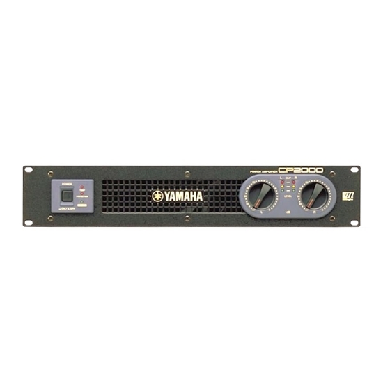
Page 6: Front Panel
11 for more information. TEMP indicator This indicator lights up if the temperature of the CP2000’s heatsinks exceed 85 degrees Celsius. Note that this indicator only serves as a warning. It does not indicate operation of the protection system. -
Page 7: Rear Panel
SPEAKERS connectors The outputs for each CP2000 channel comprise of one 1/4" phone jack and one pair of 5-way binding posts. The 1/4" phone jacks accept 1/4" phone plugs, while the 5-way binding posts offer several methods of connection, including single or double banana plugs, spade lugs, or bare wires. -
Page 8: Hookup Examples
Chapter 2—Hookup Examples GND terminal For safety reasons it’s important that the CP2000 is grounded. The attached power cord has a three-pin plug, and if the ground terminal of the AC outlet to which it is con- nected is grounded, then the CP2000 will be grounded adequately via the power cord. -
Page 9: Parallel Hookup
Channel L inputs. This mode is typically used with a mono source and allows independent volume control of two sets of speakers. The following hookup example shows how the CP2000 can be used in PARALLEL mode. -
Page 10: Bridge Mode Hookup
In BRIDGE mode, the L and R channels are combined to form a massive 2000 watt sin- gle-channel amplifier. The input signal is sourced from the Channel L inputs. The fol- lowing hookup example shows how the CP2000 can be used in BRIDGE mode. STEREO... -
Page 11: Using The Cp2000
For correct operation, it’s important that the air flow at the front and rear of the CP2000 is not blocked or restricted in any way. If the CP2000 is mounted in a portable rack with removable front and rear covers, be sure to remove the covers before using the CP2000. - Page 12 To connect an unbalanced source to an INPUT XLR, connect pin 3 (cold) to pin 1 (ground), as shown below. The following table shows which inputs, LEVEL controls, and signal and CLIP indica- tors are active in each CP2000 mode. Channel CP2000—Owner’s Manual Item...
-
Page 13: Connecting Speakers
Connecting Speakers Warning: Turn off all equipment before making any connections. The outputs for each CP2000 channel comprise of one 1/4" phone jack and one pair of 5-way binding posts. The 1/4" phone jacks accept 1/4" phone plugs, while the 5-way binding posts offer several methods of connection, including single or double banana plugs, spade lugs, or bare wire. - Page 14 Chapter 3—Using the CP2000 The following table shows which outputs can be used in each CP2000 mode and the minimum speaker impedance. Note that this is the total speaker impedance that can be connected to each channel. For example, a 2 minimum means that you could connect a single 2 speaker, two 4 speakers in parallel, or four 8 speakers in parallel.
-
Page 15: Connecting S115 And S112 Loudspeakers
Press the [POWER] switch to turn on the CP2000. The CP2000 starts up and the POWER indicator lights up. The output relay closes, connecting the speakers, several seconds after the CP2000 is turned on. Press the [POWER] switch again to turn off the CP2000. -
Page 16: Daisy Chaining Inputs
Chapter 3—Using the CP2000 disconnects the AC power when the transformer reaches a certain temperature and the POWER indicator goes out. Once the transformer has cooled down, the thermostatic cutout automatically closes, reconnecting the power, the POWER indicator lights up, and normal operation is resumed. -
Page 17: Troubleshooting
flow around the connecting the speak- amplifier. ers. The output relay closes automatically when the heatsink Contact your Yamaha has cooled down, or dealer or service cen- the DC fault is ter. removed. CP2000—Owner’s Manual... -
Page 18: Appendix
(balanced), 15 k POWER switch (push on/push off) Front panel LEVEL attenuator (31 position) x2 Mode switch (STEREO/BRIDGE/PARALLEL) Rear panel YAMAHA SPEAKER PROCESSING switch (ON/OFF) XLR-3-31 type (balanced) L+R Input 1/4" phone jack (balanced) L+R 1/4" phone jack L+R Output... -
Page 19: Dimensions
U.S.A. & Canada 120 V AC, 60 Hz Europe 230 V AC, 50 Hz Australia 240 V AC, 50 Hz 30 W 400 W 2000 W 416 mm (18.9 x 3.46 x 16.4 inches) 14 kg (30.9 lbs) 2.3 m Dimensions CP2000—Owner’s Manual... -
Page 20: Block Diagram
Block Diagram YAMAHA CORPORATION V617350 R1 1 IP 20 Pro Audio & Digital Musical Instrument Division P.O. Box 3, Hamamatsu, 430-8651, Japan NP Printed in Taiwan...