Table of Contents
Advertisement
Quick Links
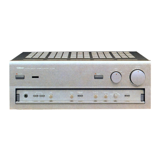
AX -890
Natural Sound Stereo Integrated Amplifier
Préampli/ampli de puissance stéréo de la série "Natural Sound"
Natural Sound Stereo-Verstärker
Natural Sound Integrerad Stereo Förstärkare
Amplificatore integrato stereo a Suono Naturale
Amplificador integrado estéreo de Sonido Natural
Natural Sound Geïntegreerde Stereo Versterker
OWNER'S MANUAL
MODE D'EMPLOI
BEDIENUNGSANLEITUNG
BRUKSANVISNING
MANUALE DI ISTRUZIONI
MANUAL DE INSTRUCCIONES
GEBRUIKSAANWIJZING
Advertisement
Table of Contents

Related Manuals for Yamaha AX-890


Summary of Contents for Yamaha AX-890
- Page 1 AX -890 Natural Sound Stereo Integrated Amplifier Préampli/ampli de puissance stéréo de la série “Natural Sound” Natural Sound Stereo-Verstärker Natural Sound Integrerad Stereo Förstärkare Amplificatore integrato stereo a Suono Naturale Amplificador integrado estéreo de Sonido Natural Natural Sound Geïntegreerde Stereo Versterker OWNER’S MANUAL MODE D’EMPLOI BEDIENUNGSANLEITUNG...
-
Page 2: Supplied Accessories
SUPPLIED ACCESSORIES ACCESSOIRES FOURNIS MITGELIEFERTES ZUBEHOR MEDFOLJANDE TILLBEHOR ACCESSORI IN DOTAZIONE ACCESORIOS INCLUIDOS BIJGELEVERDE ACCESSOIRES Remote Control Transmitter Emetteur de télécommande Fernbedienung Fjärrkontrollsändare Telecomando Transmisor del control remoto Afstandbediening This product complies with the radio frequency interference requirements of the Council Directive 82/499/EEC and/or 87/308/EEC. -
Page 3: Table Of Contents
Thank you for selecting this YAMAHA stereo amplifier. FEATURES 110W + 110W (8Ω) RMS Output Power, 0.015% THD, 20–20,000 Hz High Dynamic Power, Low Impedance Drive Capability Continuously Variable Loudness Control CD DIRECT AMPLIFIER to Reproduce the Purest CD Sound... -
Page 4: Connections
Before attempting to make any connections to or from this unit, be sure to first switch OFF the power to this unit and to any other components to which connections are being made. When making connections between this unit and other components, be sure all connections are made correctly, that is to say L (left) to L, R (right) to R, “+”... -
Page 5: Connecting Speakers
ABOUT THE OTHER REAR PANEL PARTS REMOTE CONTROL (PHONO) connector If you have a YAMAHA turntable with a terminal for remote control, connect it to this connector by using the cable provided with the turntable. This connection allows you to control the turntable from the provided remote control transmitter. -
Page 6: Operations
TO PLAY A SOURCE VOLUME –dB ∞ Set to the “ ” position. Turn the power on. POWER Select a desired input source. * If you select turntable as an input source (PHONO position), you should confirm that the PHONO (MM/MC) switch is set to the position corresponding to the type of cartridge being used by the turntable. - Page 7 TO RECORD A SOURCE TO TAPE (OR DUB FROM A TAPE TO ANOTHER) Select the source to be recorded. REC OUT TUNER TAPE COPY PHONO Play the source. Confirm the source by selecting it with the INPUT selector and turning up the VOLUME control. Set the tape deck to be used for recording in the recording mode.
-
Page 8: Selecting The Speaker System
Adjusting the BALANCE control Adjust the balance of the output volume to the left and right speakers to compensate for sound imbalance caused from speaker location or listening room conditions. BALANCE Adjusting the BASS and TREBLE controls BASS BASS : Turn this clockwise to increase (or counter- clockwise to decrease) the low frequency response. - Page 9 Using the PURE DIRECT switch You can enjoy the purest possible sound from your audio sources by setting this switch so that the indicator illuminates. By doing so, the audio signals bypass the BASS, TREBLE, SUBSONIC FILTER, BALANCE, LOUDNESS controls and the PRE OUT/MAIN IN terminals, thus eliminating any alterations to the audio signals.
-
Page 10: Remote Control Transmitter
The remote control transmitter provided with this unit is designed to control all the most commonly used functions of the unit. If the CD player, tuner, turntable and tape deck connected to this unit are YAMAHA components designed for remote control compatibility, then this remote control transmitter will also control various functions of each component. -
Page 11: Standby Mode
STANDBY mode (Europe model only) While the power is on, pressing the POWER key on the remote control transmitter switches the unit to the STANDBY mode. (In this mode, the indicator is half illuminated.) Note The POWER switch on the front panel of this unit should be turned off when left unused for a long period of time. -
Page 12: Troubleshooting
If the unit fails to operate normally, check the following points to determine whether the fault can be corrected by the simple measures suggested. If it cannot be corrected, or if the fault is not listed in the SYMPTOM column, disconnect the power cord and contact your authorized YAMAHA dealer or service center for help. SYMPTOM The unit fails to turn on when the POWER switch is pressed. -
Page 13: Specifications
SPECIFICATIONS Minimum RMS Output Power per Channel 8 ohms, 20 Hz to 20 kHz, 0.015% THD ...110W+110W 6 ohms, 20 Hz to 20 kHz, 0.03% THD ...130W+130W Dynamic Power per Channel (by IHF Dynamic Headroom measuring method) 8/6/4/2 ohms ...150/200/250/330W DIN Standard Output Power per Channel [Europe model only] (4 ohms, 1 kHz, 0.7% THD) ...185W... - Page 14 YAMAHA ELECTRONICS (UK) LTD. YAMAHA HOUSE, 200 RICKMANSWORTH ROAD WATFORD, HERTS WD1 7JS, ENGLAND YAMAHA SCANDINAVIA A.B. J A WETTERGRENS GATA 1, BOX 30053, 400 43 VÄSTRA FRÖLUNDA, SWEDEN YAMAHA MUSIC AUSTRALIA PTY, LTD. 17-33 MARKET ST., SOUTH MELBOURNE, 3205 VIC., AUSTRALIA Uitgangsniveau/Impedantie REC OUT ...150 mV/2,2 k-ohms...