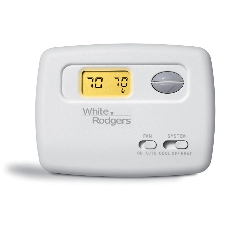
White Rodgers 1F78 User Manual
Heating & air conditioning non-programmable thermostat
Hide thumbs
Also See for 1F78:
- Installation instructions manual (17 pages) ,
- Installation instructions manual (12 pages) ,
- Installation instructions manual (16 pages)
Advertisement
Installation Instructions for
Heating & Air Conditioning
Non-Programmable Thermostat
YOUR THERMOSTAT REPLACES
Typical System Compatibility Chart
Standard Heat Only Two Wire Gas or Oil Fired Systems (24 volt)
Electronic Ignition Heat Only Two Wire Systems (24 volt)
Electronic Ignition Heat Only Gas or Oil Fired Systems (24 volt)
Standard Heat/Cool Systems (24 volt)
Heat/Cool Systems Electric Heat (24 volt)
Heat Only Electric Heat Systems (24 volt)
Cool Only Systems (24 volt)
Heat Pump Systems (No Aux or Emergency Heat)
Hot Water Zone Heat Only (Two Wire) Systems
Hot Water Zone Heat Only (Three Wire) Systems
Line Voltage Heating or Baseboard 110/240 Volt Systems
Millivolt Systems Floor or Wall Furnaces
12 VDC Mobile Home Application
Multistage Systems
Systems Exceding 30VAC, 1.5 Amp
2
THERMOSTAT DETAILS
-
Mounting
hole
W904
W905
W905
Clip for
Hydronic
System
W904
Clip for
Celsius Display
Figure 1. Thermostat base
1F78
1F78
Yes
Yes
Yes
Yes
Yes
Yes
Yes
Yes
Yes
No
No
Yes
Yes
No
No
Mounting
hole
+
-
+
W
RH
B
RC
G
O
Y
ELEC
GAS
Electric/Gas
Switch
White-Rodgers is a division
CONTENTS
Preparations .................................................. 1
Thermostat Details ........................................ 1
Removing Old Thermostat ............................ 1
Mounting and Wiring ..................................... 2
Check Thermostat Operation ........................ 3
Specifications ................................................ 5
Troubleshooting ............................................ 5
1
PREPARATIONS
Assemble tools required as shown below.
HAND OR POWER
DRILL WITH 3/16 INCH
DRILL BIT, IF NEEDED
Failure to follow and read all instructions carefully
before installing or operating this control could cause
personal injury and/or property damage
3
REMOVING OLD THERMOSTAT
To prevent electrical shock and/or equipment damage,
disconnect electrical power to the system at the main
fuse or circuit breaker until installation is complete.
Before removing wires from old thermostat's switching subbase,
label each wire with the terminal designation it was removed from.
1. Remove Old Thermostat: A standard heat/cool thermostat
consists of three basic parts:
a. The cover, which may be either a snap-on or hinge type.
b. The base, which is removed by loosening all captive screws.
c. The switching subbase, which is removed by unscrewing
the mounting screws that hold it on the wall or adaptor plate.
2. Shut off electricity at the main fuse box until installation is
complete. Ensure that electrical power is disconnected.
3. Remove the front cover of the old thermostat. With wires still
attached, remove wall plate from the wall. If the old thermostat
has a wall mounting plate, remove the thermostat and the wall
mounting plate as an assembly.
4. Identify each wire attached to the old thermostat using the
labels enclosed with the new thermostat.
5. Disconnect the wires from the old thermostat one at a time. DO
NOT LET WIRES FALL BACK INTO THE WALL.
6. Install new thermostat using the following procedures.
of Emerson Electric Co.
www.white-rodgers.com
FLAT BLADE SCREWDRIVER
WIRE CUTTER/STRIPPER
CAUTION
!
PART NO. 37-6615A
0435
Advertisement

Related Manuals for White Rodgers 1F78


Summary of Contents for White Rodgers 1F78
-
Page 1: Removing Old Thermostat
Installation Instructions for Heating & Air Conditioning 1F78 Non-Programmable Thermostat YOUR THERMOSTAT REPLACES Typical System Compatibility Chart Standard Heat Only Two Wire Gas or Oil Fired Systems (24 volt) Electronic Ignition Heat Only Two Wire Systems (24 volt) Electronic Ignition Heat Only Gas or Oil Fired Systems (24 volt) -
Page 2: Mounting And Wiring
REMOVING OLD THERMOSTAT CONTINUED FROM FIRST PAGE ATTENTION! This product does not contain mercury. How- ever, this product may replace a unit which contains mercury. Do not open mercury cells. If a cell becomes damaged, do not touch any spilled mercury. Wearing non-absorbent gloves, take up the spilled mercury and place into a container which can be sealed. -
Page 3: Check Thermostat Operation
MOUNTING AND WIRING CONTINUED FROM SECOND PAGE Heating Relay System NOTE For 2-wire Heat only, attach to RH and W Figure 2. Typical wiring diagram for heat only, 3-wire, single transformer systems Cooling System Relay Figure 3. Typical wiring diagram for cool only, 3-wire, single transformer systems NOTE RED jumper wire (provided with thermostat) must be... -
Page 4: Display View
CHECK THERMOSTAT OPERATION CONTINUED FROM THIRD PAGE Before you begin using your thermostat, you should be familiar with its features and with the display and the location and operation of the thermostat buttons. Your thermostat consists of two parts: the thermostat cover and the base. To remove the cover, gently pull it straight out from the base. -
Page 5: Specifications
SPECIFICATIONS ELECTRICAL DATA Electrical Rating: 0 to 30 VAC 50/60 Hz. or D.C. 0.05 to 1.0 Amps (Load per terminal) 1.5 Amps Maximum Total Load (All terminals combined) TROUBLESHOOTING Reset Operation If a voltage spike or static discharge blanks out the display or causes erratic thermostat operation you can reset the thermo- stat by pressing at the same time while moving... - Page 6 TROUBLESHOOTING CONTINUED FROM FIFTH PAGE Symptom Heat, Cool or Fan Runs Constantly. Furnace Cycles Too Fast or Too Slow (narrow or wide temperature swing) Cooling Cycles Too Fast or Too Slow (narrow or wide temperature swing) Thermostat Setting and Thermostat Thermometer Disagree Blank Display and/or Keypad Not Responding...