Whirlpool WHES40 Installation And Operation Manual
Demand controlled water softener
Hide thumbs
Also See for WHES40:
- Installation and operation manual (24 pages) ,
- Performance data sheet (1 page) ,
- Installation and operation manual (19 pages)
Table of Contents
Advertisement
Quick Links
TM
Model WHES40
How to install, operate and
maintain your Demand
Controlled Water Softener
Do not return water softener to store
If you have questions or concerns when
installing, operating or maintaining your
softener, call our toll free number:
1-866-986-3223
Monday - Friday, 8 am - 9 pm EST
7262970 (Rev. D 9/22/04)
Product No. 8562922
Advertisement
Table of Contents

Related Manuals for Whirlpool WHES40


Summary of Contents for Whirlpool WHES40
- Page 1 Model WHES40 How to install, operate and maintain your Demand Controlled Water Softener Do not return water softener to store If you have questions or concerns when installing, operating or maintaining your softener, call our toll free number: 1-866-986-3223 Monday - Friday, 8 am - 9 pm EST 7262970 (Rev.
-
Page 2: Table Of Contents
Table of Contents Water Softener Safety Before You Start Inspect Shipment Water Softener Dimensions How a Water Softener Works ... Softening Cycle Regeneration Cycle ... Water Conditioning Information Water Conditioning Installation Requirements Location Requirements Tools and Parts Needed ... Air Gap Requirements Valve Drain Requirements Plan the Installation Inlet - Outlet Plumbing Options ... -
Page 3: Water Softener Safety
Water Softener Safety Your safety and the safety of others are very important. We have provided many important safety messages in this manual and on your appliance. Always read and obey all safety messages. This symbol alerts you to potential hazards that can kill or hurt you and others. All safety messages will follow the safety alert symbol and either the word "DANGER"... -
Page 4: Inspect Shipment
Inspect Shipment The parts required to assemble and install the water softener are included with the water softener. Copper tubes and ground clamp Hose adaptor Drain line adaptor Grommet Thoroughly check the water softener tk)r possible shipping damage and parts loss. Also inspect and note any damage to the shipping carton. -
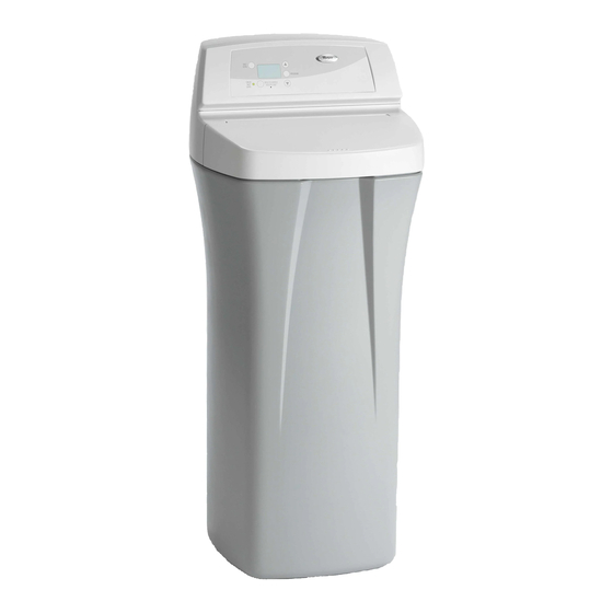
Page 5: Water Softener Dimensions
Water Softener Dimensions MODEL WHES40 How a Water Softener Works Softening Cycle When the water softener is providing soft water, it is called "service" or the "softening cycle". During this cycle, hard water flows from the main water pipe in the household into the water softener. Inside the resin tank is a bed made up of thousands of tiny, plastic resin beads. -
Page 6: Water Conditioning Information
Water Conditioning Water Conditioning Water conditioning Hardness Iron Acidity Sediments Hardness chemical analysis accurately measures the amount of minerals in grain weight. For example, one gallon of water with 5 grains per gallon (gpg) hardness has dissolved minerals, that if solidified, about equals the size of one ordinary aspirin tablet. - Page 7 Iron in water can cause stains on clothing and plumbing fixtures. It can negatively affcct the taste of tk)od, drinking water, and other beverages. Iron in water is measured in parts per million (ppm). The total* ppm of iron, and type or types*, is determined by chemical analysis. Four different types of iron in water are: Ferrous (clear water), Ferric (red water),...
-
Page 8: Installation Requirements
Installation Requirements Tools and Parts Needed Assemble the required tools before starting installation. Read and %llow tile instructious provided with any tools listed here. • Screwdriver • Pliers If using Soldered • Tubing cutter • Propane torch • Misc. copper pipe fittings If using Threaded •... -
Page 9: Air Gap Requirements
Air Gap Requirements A drain is needed for regeneration preferred. A laundry tub, standpipe, etc., are other drain options. Secure valve drain hose in place. t-1/z' airgap floor drain Figure 2 Valve Drain Requirements Use the flexible green drain hose, that is included, measure and cut to the length needed. Flexible drain hose is not allowed in all localities (check your plumbing codes). -
Page 10: Plan The Installation
Plan the Installation Inlet - Outlet Plumbing Options Always install either a single bypass valve (provided) or, if desired, parts tk)r a 3 valve bypass system (not included) can be purchased and assembled, as shown in Figure 4. Bypass valves allow you to turn off water to the softener tk_rmaintenance •... -
Page 11: Installation Instructions
Installation Instructions Turn Off Water Supply Close the main water supply valve, near the well pump or water meter. Open all faucets to drain all water from the house pipes. NOTE: Install the Brine Tank Overflow Install the brine tank overflow grommet and elbow in the 13/16" diameter hole in the back of the salt storage tank sidewall. -
Page 12: Move The Water Softener Into Place
Move the Water Softener into Place Move the water softener into desired location. Set it on a level surface. If needed, place the water softener on a section of plywood, a minimum of 3/4" thick. Then, shim under the plywood to level the water softener, see Figure 7. -
Page 13: Assemble Inlet And Outlet Plumbing
Assemble Inlet and Outlet Plumbing Measure, cut, and loosely assemble pipe and fittings from the main water pipe to the inlet and outlet ports of the water softener valve. Be sure to keep fittings fully together, and pipes squared and straight. Be sure hard water supply pipe goes to the water softener valve inlet side. -
Page 14: Install Valve Drain Hose
Threaded pipe Apply pipe joint compound or Teflon ® tape to all male pipe threads. Tighten all threaded joints and make all solder connections. NOTE: IMPORTANT: CPVC plastic pipe Clean, prime and cement all joints, following the malmfacturer's plastic pipe and fittings. NOTE: IMPORTANT: Other... -
Page 15: Test For Leaks
Test for Leaks To prevent air pressure in the water softener and plumbing system, do the %llowing Fully open two or more softened downstream Place the single valve bypass valve or 3 valve bypass in "bypass" Installation" Fully open the main water supply valve. Run water until there is a steady flow from the opened faucets, with no air bubbles. -
Page 16: Program The Water Softener
Program the Water Softener SET SALT LEVEL button TANK LIGHT button RECHARGE button Figure If you have questions about installation, When the water softener is plugged in, a model code and a test number (example: J1.0), begin to flash in the faceplate display. Then, "12:00 PM" and the ",w rds CURRENT NOTE: Set Time of Day If the words "CURRENT... -
Page 17: Set Water Hardness Number
Set Water Hardness Number Press the O Press the _ NOTE: Set Recharge (Regeneration) Press the _ "RECHARGE water is not in use. If you want to change the recharge start time, press the _ desired starting time shows. Set Salt Type Press the _ Salt Type alk)ws you to choose between sodium chloride (NaC1), which is regular softener salt, or potassium chloride (KC1), which is an alternative to sodium chloride. -
Page 18: Start A Recharge
Check the brine tank and brinewell present, pour small amounts of warm water on hardened areas until they loosen; Be sure to set the correct salt type depending Use the _ PROGRAM Press the O Start a Recharge Press the O display, starting a recharge. -
Page 19: Customize Features/Options
Customize Features/Options Recharge Recharge button is used to initiate an immediate recharge. Press and hold the O and "FILL" flash in the display, and the softener enters the fill cycle of regeneration away. conditioning remaining until the recharge is completed will show in the display during all cycles except for the Fill cycle. -
Page 20: Tank Light
Tank Light The softener is equipped with a tank light for viewing the salt level in the brine tank. Push the tank light button on the electronic control once and the tank light will turn on. Pushing the tank light button again will turn the light off. -
Page 21: Clean / Clear Water Iron Removal
Clean / Clear Water Iron Removal This fcature is beneficial silt, dirt, etc.). Default setting is "OFF". When set to "ON", an additional backwash and fast rinse cycle will occur first, preceeding the normal regeneration bed betk)re it is regenerated with the salt brine. To conserve water set this fcature "OFF" if your water supply does not contain iron or sediments. -
Page 22: Maximum Days Between Regenerations
Maximum Days Between Regenerations The water softener automatically efficiency, and under most conditions, this fcature should be left in this mode. However, modify this feature if you want to force a regeneration contains iron and you want the softener to regenerate bed clean, set the display as shown below. -
Page 23: Routine Maintenance
Routine Maintenance Refilling With Salt Lift the salt hole cover and check the salt storage level frequently. bef\)re you refill it, you will get hard water. Until you have established salt every two or three weeks. Always refill if less than 1/3 full. Be sure the brinewell cover is on. NOTE: Recommended Salt Not Recommended:... -
Page 24: Cleaning The Nozzle And Venturi
Cleaning the Nozzle and Venturi A clean nozzle and venturi (see Figure 12) is a must for the conditioner to work properly. This small water softener creates the suction to move brine from the brine tank, into the resin tank. If it should become plugged with sand, silt, dirt, etc., the conditioner will not work, and you will get hard water. -
Page 25: Troubleshooting Guide
Troubleshooting Need help troubleshooting? Tools Needed For Most Repairs: 5/16 Hex Driver, Phillips Screwdriver, Needle-nose PROBLEM No Soft Water 1. No salt in the storage tank. No Soft Water Timer 1. Transformer Display Blank disconnected defective. Fuse blown, circuit breaker popped, (See page 20 "Power Outage Memory"). -
Page 26: Automatic Electronic Diagnostics
Automatic Electronic Diagnostics This water softener has a self-diagnostic water meter). The water softener monitors electronic If a malfunction The troubleshooting each code. While an error code appears in the display, all buttons are inoperable except the PROGRAM PROGRAM see below, to further isolate the problem. Manual Advance Diagnostics Use the following procedures operation. -
Page 27: Manual Advance Regeneration Check
NOTE: While in this diagnostic screen, the following information various reasons. This information is applied to the face plate. Press _ applied. Press _ since the LEcode number was entered. Press and hold the _ This code identifies the softener model. If the wrong number shows, the softener will operate on incorrect programming. - Page 28 NSF/ANSI 44 Ik)r the specific by test data. Standard 44. controls at regeneration flow plug, or drain hose. RECHARGE button. WHES40 1.17 20 - 125 40 - 120 200 Ibs. WHES40 18,000 @ 3.5 30,900 @ 7.0 40,000 @ 11.2 5,200 @ 3.5 Ibs.
-
Page 29: Wiring Schematic
This warranty applies to consumer-owned of Whirlpool, USA, used under license. of E. I. DuPont. c .-- .-- o._NO Position switch Drive, Woodbury,... -
Page 30: Softener Components
Softener Components 32 -_----_... - Page 31 Softener Components Part No. Description 7170296 O-Ring, 2-7/8" x 3-1/4" 7170254 O-Ring, 13/16" x 1-1/16" 7077870 Top Distributor 7170270 O-Ring, 2-3/4" x 3" 7105047 Rep'l Bottom Distributor 7176292 Clamp Section (2 req.) 7088033 Retainer Clip (2 req.) 7247996 Rep'l Resin Tank 0502272 Resin, 1 cu.
- Page 32 Softener Components flow plug assembly assembled...
- Page 33 Softener Components Part No. Description 7224087 Screw, #8-32 x 1" (2 req.) 7250622 Motor (incl. 2 ea. of Key No. 1) 7231393 Motor Plate 0900857 Screw, #6-20 x 3/8 (3 req.) 7171250 Bearing 7219545 Cam and Gear 7169180 Clip (Drain) 0900431 Itose Clamp...
- Page 34 Notes...
- Page 35 Notes...
- Page 36 3/04...