Table of Contents
Advertisement
Model No. WESY3924.2
Serial No.
Write the serial number in the
space above for future reference.
Serial Number Decal (under seat)
QUESTIONS?
As a manufacturer, we are com-
mitted to providing complete
customer satisfaction. If you
have questions, or if a part is
damaged or missing, PLEASE
CONTACT OUR CUSTOMER
SERVICE DEPARTMENT
DIRECTLY.
CALL TOLL-FREE:
1-877-992-5999
Mon.–Fri., 6 a.m.–6 p.m. MST
ON THE WEB:
www.weiderservice.com
CAUTION
Read all precautions and instruc-
tions in this manual before
using this equipment. Save this
manual for future reference.
USER'S MANUAL
Visit our website at
www.weiderfitness.com
new products, prizes,
fitness tips, and much more!
Advertisement
Table of Contents

Related Manuals for Weider WESY3924.2


Summary of Contents for Weider WESY3924.2
- Page 1 Model No. WESY3924.2 Serial No. Write the serial number in the space above for future reference. Serial Number Decal (under seat) QUESTIONS? As a manufacturer, we are com- mitted to providing complete customer satisfaction. If you have questions, or if a part is...
-
Page 2: Table Of Contents
Apply the decal in the location shown. Keep hands and fingers clear of this area. MAX by WEIDER is a trademark of ICON IP, Inc. -
Page 3: Important Precautions
13. The resistance system is designed to be used with the included resistance, and the resistance included with a MAX by WEIDER MAX PACK. Do not use the resistance sys- tem with any other type of resistance. -
Page 4: Before You Begin
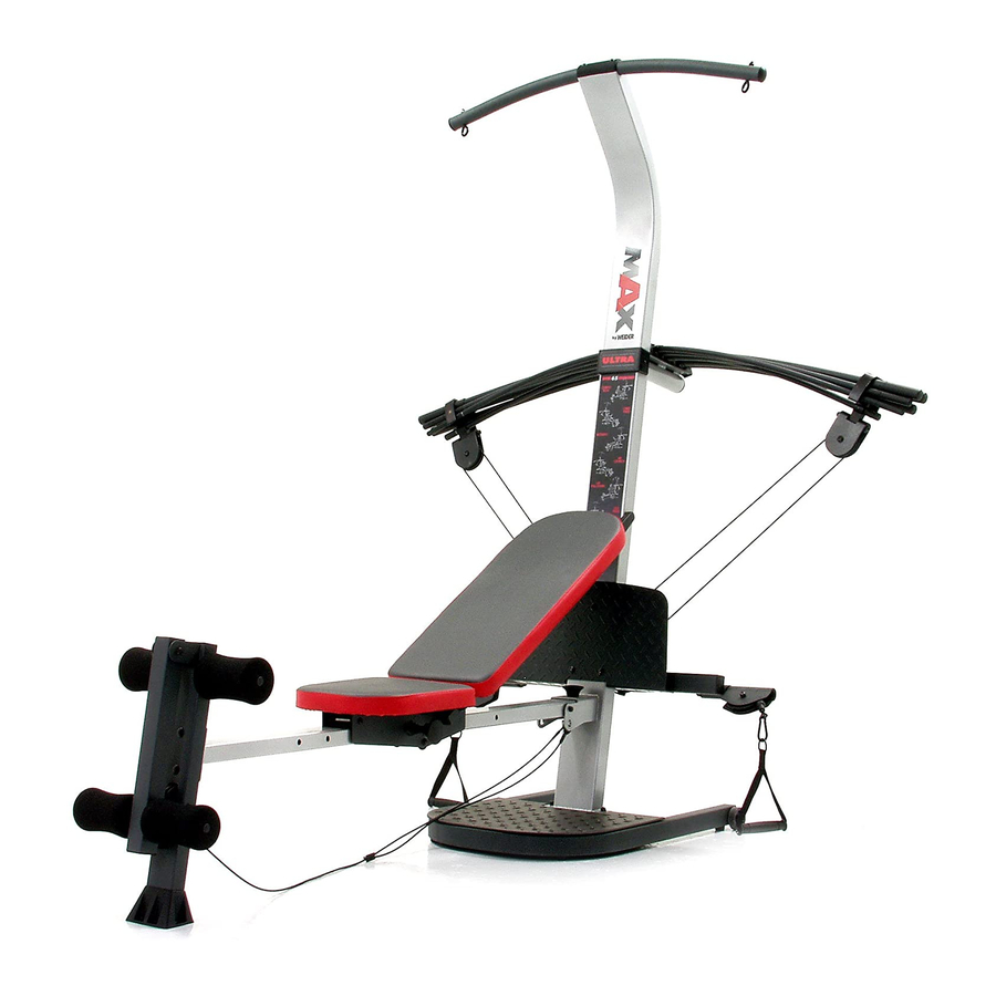
BEFORE YOU BEGIN Thank you for selecting the innovative MAX by WEI- ® ULTRA resistance system. The resistance system offers a selection of stations designed to develop every major muscle group of the body. Whether your goal is to tone your body, build dramatic muscle size and strength, or improve your cardiovascular system, the resistance system will help you to achieve the specific results you want. -
Page 5: Assembly
ASSEMBLY Make Things Easier for Yourself This manual is designed to ensure that the resist- ance system can be assembled successfully by most people. However, it is important to realize that the versatile resistance system has many parts and that the assembly process will take time. - Page 6 2. Attach a Wheel (31) to the outside of the Base (1) with an M10 x 78mm Bolt (81), three M10 Washers (75), and an M10 Nylon Locknut (76). Do not overtighten the Locknut; the Wheel must be able to turn easily. Attach the other Wheel (not shown) in the same manner.
- Page 7 6. Attach the Lat Tower (4) to the Upright (3) with four M10 x 25mm Button Head Screws (87), and four M10 Lock Washers (68). Attach the Name Plate (89) to the Lat Tower (4) with two M4 x 16mm Screws (62). 7.
- Page 8 9. Attach two 8mm Metal Spacers (91), a 60mm Metal Spacer (39), and two Bearing Wheels (46) to one end of the Seat Carriage (12) with an M8 x 104mm Button Head Bolt (60) and an M8 Nylon Locknut (65) as shown. Make sure that the parts are oriented as shown in the inset drawing;...
- Page 9 12. Attach a Plastic Foot (53) to the Backrest Frame (15) with an M4 x 16mm Screw (62). Attach the two Guard Plates (17) to the inside of the Backrest Frame (15) with four M4 x 16mm Screws (62). 13. Orient the Backrest (14) as shown. Attach the Backrest to the Backrest Frame (15) with four 1/4”...
- Page 10 15. Locate the fulcrum on the Lat Tower (4) (see the inset drawing). Slide the Tray (35) onto the rods on the fulcrum. Make sure the Tray is oriented as shown in the drawing. Set the Resistance Bars into the Tray (35) in the following order: the 10-pound Resistance Bar (67), the 20-pound Resistance Bar (36), an 80-pound Resistance Bar (95), the 10-pound Center...
- Page 11 19. Wrap the Long Cable (80) under a 90mm Pulley (28) as shown. Attach the Pulley and a Cable Trap (29) to the Upright (3) with an M10 x 120mm Button Head Bolt (40) and an M10 Nylon Locknut (76). Make sure the Cable Trap is oriented to hold the Cable in the groove of the Pulley.
- Page 12 23. Locate the Leg Lever Cable (32), which has two ends that are the same length and a third end that is longer. Route the longest end of the Leg Lever Cable (32) through the hole in the Front Leg (6), and attach it inside of the hole in the Leg Lever (7) with an M10 x 50mm Bolt (63) and an M10 Nylon Locknut (76).
-
Page 13: Adjustments
ADJUSTMENTS This section explains how to adjust the resistance system. See the EXERCISE GUIDELINES on page 17 for important information about how to get the most benefit from your exercise program. Also, refer to the accompa- nying exercise guide to see the correct form for each exercise. Make sure all parts are properly tightened each time the resistance system is used. - Page 14 ATTACHING THE ACCESSORIES To attach a Handle (49) to a high pulley, first attach the high pulley to the resistance system (see ATTACHING THE HIGH PULLEYS AND LEG LEVER on page 13). Then, attach the Handle to the Short Cable (33) with a Cable Clip (51).
-
Page 15: Adjusting The Backrest
ADJUSTING THE BACKREST The Backrest (14) can be used in a level position or one of three inclined positions. To use the Backrest in a level position, secure the Seat Carriage (12) to the adjustment hole in the Bench Rail (5) next to the Front Leg (6) (see ADJUSTING THE SEAT on page 13). -
Page 16: Cable Diagram
CABLE DIAGRAM The cable diagram shows the proper routing of the Long Cable (80). Use the diagram to make sure that Long Cable (80) the Cable has been assembled correctly. If the Cable has not been correctly routed, the resistance system will not function properly and damage may occur. -
Page 17: Exercise Guidelines
EXERCISE GUIDELINES THE FOUR BASIC TYPES OF WORKOUTS Muscle Building To increase the size and strength of your muscles, push them close to their maximum capacity. Your mus- cles will continually adapt and grow as you progres- sively increase the intensity of your exercise. You can adjust the intensity level of an individual exercise in two ways: •... -
Page 18: Muscle Chart
Rest for a short period of time after each set. The ideal resting periods are: • Rest for three minutes after each set for a muscle building workout. • Rest for one minute after each set for a toning work- out. - Page 19 EXERCISE MONDAY Date: AEROBIC EXERCISE TUESDAY Date: EXERCISE WEDNESDAY Date: THURSDAY AEROBIC EXERCISE Date: EXERCISE FRIDAY Date: Make photocopies of this page for scheduling and recording your workouts. RESISTANCE RESISTANCE RESISTANCE SETS REPS SETS REPS SETS REPS...
-
Page 20: Part Identification Chart
PART IDENTIFICATION CHART Refer to the drawings below to identify small parts used in assembly. The number in parentheses below each drawing is the key number of the part, from the PART LIST on the reverse side of this page. Note: Some small parts may have been pre-attached. - Page 21 M10 x 65mm Button Head Screw (70) M10 x 68mm Bolt (56) M10 x 66mm Carriage Bolt (83) M10 x 72mm Bolt (64) M10 x 78mm Bolt (81) M10 x 91mm Bolt (90) M10 x 103mm Bolt (66) M8 x 104mm Button Head Bolt (60) M10 x 102mm Button Head Bolt (24) M8 x 114mm Axle (57) M10 x 120mm Button Head Bolt (40)
-
Page 22: Part List
PART LIST—Model No. WESY39242 Key No. Qty. Description Base Base Plate Upright Lat Tower Bench Rail Front Leg Leg Lever M4 x 5mm Screw Large Plastic Foot Top Frame Cross Tube Seat Carriage Seat Backrest Backrest Frame Backrest Cap Guard Plate 10-pound Resistance Bar Cap M8 Flange Nut 10-pound Short Resistance Bar... - Page 23 EXPLODED DRAWING—Model No. WESY39242 89 62 76 28 R0805A...
-
Page 24: Ordering Replacement Parts
• the MODEL NUMBER of the product (WESY3924.2) • the NAME of the product (MAX by WEIDER ULTRA resistance system) • the SERIAL NUMBER of the product (see the front cover of this manual) • the KEY NUMBER and DESCRIPTION of the part(s) (see the PART LIST and EXPLODED DRAWING in the...