Table of Contents
Advertisement
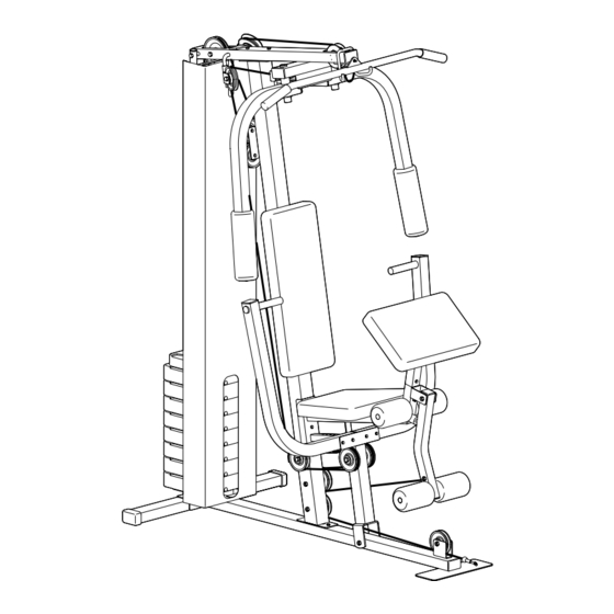
Model No. WESY19001
Serial No.
Write the serial number in the
space above for reference.
Serial Number Decal (under seat)
QUESTIONS?
As a manufacturer, we are
committed to providing complete
customer satisfaction. If you
have questions, or if there are
missing parts, we will guarantee
complete satisfaction through
direct assistance from our factory.
TO AVOID UNNECESSARY
DELAYS, PLEASE CALL DIRECT
TO OUR TOLL-FREE CUSTOMER
HOT LINE. The trained techni-
cians on our customer hot line
will provide immediate assis-
tance, free of charge to you.
CUSTOMER HOT LINE:
1-800-999-3756
Mon.–Fri., 6 a.m.–6 p.m. MST
CAUTION
Read all precautions and instruc-
tions in this manual before using
this equipment. Save this manual
for future reference.
®
USER'S MANUAL
Visit our website at
www.weiderfitness.com
new products, prizes,
fitness tips, and much more!
Advertisement
Table of Contents

Related Manuals for Weider WESY19001


Summary of Contents for Weider WESY19001
- Page 1 Model No. WESY19001 Serial No. Write the serial number in the space above for reference. Serial Number Decal (under seat) QUESTIONS? As a manufacturer, we are committed to providing complete customer satisfaction. If you have questions, or if there are...
-
Page 2: Table Of Contents
LIMITED WARRANTY ............Back Cover WEIDER is a registered trademark of ICON Health & Fitness, Inc. -
Page 3: Important Precautions
IMPORTANT PRECAUTIONS WARNING: To reduce the risk of serious injury, read the following important precautions before using the training system. 1. Read all instructions in this manual and in the accompanying literature before using the training system. 2. It is the responsibility of the owner to ensure that all users of the training system are ade- quately informed of all precautions. -
Page 4: Before You Begin
Friday, 6 a.m. until 6 p.m. Mountain Time (excluding holidays). To help us assist you, please note the product model number and serial number before calling. The model number is WESY19001. The ® serial number can be found on a decal attached to the training system (see the front cover of this manual). -
Page 5: Part Identification Chart
PART IDENTIFICATION CHART This chart is provided to help you identify the small parts used in assembly. The number in parenthesis below each part refers to the key number of the part, from the PART LIST on page 22. Important: Some parts may have been pre-assembled for shipping purposes. - Page 6 1/4" x 2 1/4" Carriage Bolt (38) 5/16" x 2 1/2" Bolt (22) 3/8" x 2 1/2" Bolt (7) 3/8" x 2 3/4" Bolt (85) 1/4" x 3" Bolt (43) 5/16" x 3 1/4" Bolt (14) 3/8" x 3 1/4" Bolt (8) 3/8"...
-
Page 7: Assembly
ASSEMBLY Make Assembly Easier for Yourself Everything in this manual is designed to ensure that the training system can be assembled successfully by anyone. Before beginning assembly, make sure to read the information on this page; this brief intro- duction will save you much more time than it takes to read it. - Page 8 1. Press a 1 1/2” x 2 1/2” Outer Cap (73) onto each end of the Stabilizer (5). Press a 1 1/2” x 2 1/2” Inner Cap (27) into the indicated end of the Base (4). Attach the Base (4) to the Stabilizer (5) using two 3/8”...
- Page 9 5. Insert the Weight Tube Cap (72) into the indi- cated end of the Weight Tube (63). Slide the Weight Tube into the center holes in the Weights (25). Slide the Top Weight (56) down onto the Weight Guides (62) as shown. 6.
- Page 10 8. Attach the Top Frame (55) to the Weight Guides (62) using a 5/16” x 6” Bolt (60), two 1/2” x 1/2” Spacers (61), and a 5/16” Nylon Locknut (3) as shown. Tighten all Nylon Locknuts used in steps 3 through 8.
- Page 11 11. Attach the Seat Plate (37) to the Seat Frame (36) using a 1/4” x 2 1/4” Carriage Bolt (38), a 1/4” Flat Washer (78), and a 1/4” Nylon Locknut (2). 12. Attach a Bumper (11) to the Seat Frame (36) using a #10 x 1”...
- Page 12 15. Press a 1 3/4” Square Inner Cap (44) into the lower end of the Left Arm (47). Using a small amount of soapy water, slide a Foam Arm Pad (45) onto the Left Arm. Assemble the Right Arm (48, not shown) in the same manner.
- Page 13 19. Route the Short Cable (23) around two “V”- Pulleys (6). Attach the “V”-Pulleys and two Long Cable Traps (50) to the Left Arm (47) and the Right Arm (48) as shown, using two 3/8” x 2 1/2” Bolts (7) and two 3/8” Nylon Locknuts (21).
- Page 14 23. Important: As you assemble the Long Cable (69) in steps 23–30, refer to the Cable Diagram on page 21. Route the Long Cable (69) between the Base (4) and the Press Frame (17) as shown. Lay the Long Cable in the bracket on the Base. Attach the Pro-Pulley (77) to the bracket using a 3/8”...
- Page 15 27. Route the Long Cable (69) behind the Press Frame (17) and under the Seat Frame (36) as shown. Route the Long Cable (69) around two 3 1/2” Pulleys (15). Slide the 3/8” x 5” Bolt (75) through the 3 1/2” Pulleys (15), two Cable Traps (66), and the Press Frame (17) as shown.
- Page 16 31. Attach the Seat (13) to the Seat Frame (36) using two 1/4” x 3/4” Bolts (18), a 1/4” x 2 1/4” Bolt (33), and a 1/4” Flat Washer (78). 32. Attach the Backrest (41) to the Front Upright (42) using two 1/4” x 3” Bolts (43) and two 1/4”...
- Page 17 35. Attach the Shroud (59) to the brackets on the Top Frame (55) and the Base (4) using four #8 x 1/2” Screws (79). 36. Make sure that all parts have been properly tightened. The use of the remaining parts will be explained in ADJUSTMENT, beginning on page 18 of this manual.
-
Page 18: Adjustment
ADJUSTMENT The instructions below describe how each part of the training system can be adjusted. Refer to the exercise guide accompanying this manual to see how the training system should be used for each exercise. IMPOR- TANT: When attaching the lat bar or nylon strap, make sure that the attachments are in the correct start- ing position for the exercise to be performed. -
Page 19: Weight Resistance Chart
WEIGHT RESISTANCE CHART This chart shows the approximate weight resistance at each exercise station. “Top” refers to the 6.5 lb. top weight. The other numbers refer to the 10 lb. weight plates. The butterfly arm resistance listed is the resistance for each butterfly arm.The actual resistance at each weight station may vary due to differences in individ- ual weight plates, as well as friction between the cables, pulleys, and weight guides. -
Page 20: Trouble-Shooting And Maintenance
TROUBLE-SHOOTING AND MAINTENANCE Inspect and tighten all parts each time you use the training system. Replace any worn parts immediately. The training system can be cleaned using a damp cloth and mild non-abrasive detergent. Do not use solvents. TIGHTENING THE CABLES Woven cable, the type of cable used on the training system, can stretch slightly when it is first used. -
Page 21: Cable Diagram
CABLE DIAGRAM The diagram below shows the proper routing of the Short Cable (23) and the Long Cable (69). Use the diagram to be sure that the cables and the cable traps have been assembled correctly. If the cables have not been cor- rectly routed, the training system will not function properly and damage may occur. -
Page 22: Part List
PART LIST—Model No. WESY19001 Key No. Qty. Description 3/8” x 2 1/4” Carriage Bolt 1/4” Nylon Locknut 5/16” Nylon Locknut Base Stabilizer “V”-Pulley 3/8” x 2 1/2” Bolt 3/8” x 3 1/4” Bolt 3/8” Flat Washer 1” Inner Cap Bumper 3/8”... -
Page 23: Exploded Drawing
EXPLODED DRAWING—Model No. WESY19001 11 80 R0201A... -
Page 24: Ordering Replacement Parts
Friday, 6 a.m. until 6 p.m. Mountain Time (excluding holidays). To help us assist you, please be pre- pared to give the following information: • The MODEL NUMBER of the product (WESY19001) • The NAME of the product (WEIDER •...