Table of Contents
Advertisement
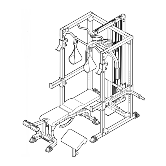
Model No. WEBE37332
Serial No.
Write the serial number in the
space above for future reference.
Serial Number Decal (Under Seat)
QUESTIONS?
As a manufacturer, we are com-
mitted to providing complete
customer satisfaction. If you
have questions, or if there are
missing or damaged parts, we
will guarantee complete satis-
faction through direct assis-
tance from our factory.
TO AVOID DELAYS, PLEASE
CALL DIRECT TO OUR TOLL-
FREE CUSTOMER HOT LINE.
The trained technicians on our
customer hot line will provide
immediate assistance, free of
charge.
CUSTOMER HOT LINE:
1-800-999-3756
Mon.–Fri., 6 a.m.–6 p.m. MST
CAUTION
Read all precautions and instruc-
tions in this manual before using
this equipment. Save this manual
for future reference.
USER'S MANUAL
Visit our website at
www.weiderfitness.com
new products, prizes,
fitness tips, and much more!
Advertisement
Table of Contents

Summary of Contents for WEIDER CLUB C670
- Page 1 Model No. WEBE37332 Serial No. Write the serial number in the space above for future reference. Serial Number Decal (Under Seat) QUESTIONS? As a manufacturer, we are com- mitted to providing complete customer satisfaction. If you have questions, or if there are missing or damaged parts, we will guarantee complete satis- faction through direct assis-...
-
Page 2: Table Of Contents
Note: A PART IDENTIFICATION CHART and a PART LIST/EXPLODED DRAWING is attached in the center of this manual. Remove the PART IDENTIFICATION CHART and PART LIST/EXPLODED DRAWING before begin- ning assembly. WEIDER is a registered trademark of ICON Health & Fitness, Inc. -
Page 3: Warning Decal Placement
WARNING DECAL PLACEMENT The decals shown here have been placed on the weight bench. If a decal is missing or illegible, please call our Customer Service Department toll-free at 1-800-999-3756, Monday through Friday, 6 a.m. until 6 p.m. Mountain Time, to order a free replacement decal. -
Page 4: Important Precautions
IMPORTANT PRECAUTIONS WARNING: To reduce the risk of serious injury, read the following important precautions before using the weight bench. 1. Read all instructions in this manual before using the weight bench. Use the weight bench only as described in this manual. 2. -
Page 5: Before You Begin
BEFORE YOU BEGIN Thank you for selecting the versatile WEIDER C670 weight bench. The weight bench offers a selec- tion of weight stations designed to develop every major muscle group of the body. Whether your goal is to tone your body, build dramatic muscle size and strength, or improve your cardiovascular system, the weight bench will help you to achieve the specific results you want. -
Page 6: Assembly
ASSEMBLY Make Things Easier for Yourself Everything in this manual is designed to ensure that the weight bench can be assembled suc- cessfully by anyone. However, it is important to realize that the versatile weight bench has many parts and that the assembly process will take time. - Page 7 2. Attach a Small Base Cap (20) to the Bench Base (3) with two M4 x 16mm Screws (36). Attach the other Small Base Cap in the same manner. Press the 51mm x 76mm Inner Cap (14) into the indicated end of the Bench Leg (4). Attach the Bench Leg (4) to the Bench Base (3) with four M10 x 71mm Bolts (31), two Bench Base Joint Plates (25), and four M10 Nylon...
- Page 8 6. Pull out the Small Adjustment Knob (23) that is nearer the Stabilizer (2). Insert the Backrest Bracket (16) between the tubes on the Bench Frame (1) and engage the Small Adjustment Knob into one of the holes in the Bracket. Pull out the Small Adjustment Knob (23) by the (93).
- Page 9 10. Press two 25mm Square Inner Caps (28) into a Pad Tube (27). Slide the Pad Tube into a hole in the Leg Lever (5). Slide two Foam Pads (26) onto the Pad Tube. Assemble the other Pad Tube (27) in the same manner.
- Page 10 13. Attach a Rear Upright (43) to the Left Base (40) with two M10 x 78mm Bolts (32) and two M10 Nylon Locknuts (34). Note: The Rear Uprights are shorter than the Front Uprights (not shown). Make sure the holes are on the side shown.
- Page 11 15. Loosen the two Adjustment Knobs (22) on the Left Safety Spotter (51) by turning them counter- clockwise. Pull both Knobs out at the same time and slide the Left Safety Spotter (51) onto the Left Uprights (43, 44) and engage and tighten the Adjustment Knobs (22) into a set of holes in the Uprights.
- Page 12 18. Attach the Chin-up Bar (54), with the bends going up, to the Left Front Upright (44) and the Left Top Frame (48) with four M10 x 78mm Bolts (32), a Rack Joint Plate (85), and four M10 Nylon Locknuts (34). Do not tighten the Locknuts yet. Attach the Chin-up Bar (54) to the Right Front Upright (not shown) and the Right Top Frame (not shown) in the same manner.
- Page 13 20. Press a 60mm Square Inner Cap (64) into the Weight Guide Base (41). Attach the Foot Plate (67) and the Weight Guide Base (41) to the Center Base (39) with two M10 x 81mm Button Bolts (104) and two M10 Nylon Locknuts (34).
- Page 14 23. Press two 48mm Weight Carriage Caps (63) into the Weight Carriage (62). Insert an M10 x 19mm Bolt (102) into the bracket on the Weight Carriage (62) from the side shown. Slide the Weight Carriage (62) onto the Weight Guide Upright (42) so that the weight tube is toward the Center Upright (45).
- Page 15 26. Press a 50mm Square Inner Cap (13) and a 25mm Square Inner Cap (28) into the Right Butterfly Arm (56). Press two Plastic Butterfly Bushings (79) and two Metal Butterfly Bushings (113) into the Arm. Wet the bottom of the Butterfly Arm with soapy water and slide a Butterfly Foam Pad (66) onto the Arm.
- Page 16 29. Locate the Medium Cable (69). Route the Cable up through the Weight Guide Top Frame (49) and over a Pulley (87). Attach the Pulley inside the Top Frame with an M10 x 75mm Bolt (92), two M10 Washers (35), two 17mm Spacers (89), and an M10 Nylon Locknut (34).
- Page 17 34. Locate the Butterfly Cable (109). Attach the Cable to the Left Butterfly Arm (57) with an M8 x 43mm Shoulder Bolt (107), an M10 Small Washer (95), and an M8 Nylon Locknut (108). 35. Wrap the Butterfly Cable (109) over a “V”-pulley (86).
- Page 18 39. Locate the Long Cable (68). Route the eyelet end of the Cable through the Foot Plate (67) and the Center Upright (45), and under a Pulley (87). Attach the Pulley (87) inside the Center Upright (45) with an M10 x 75mm Bolt (92), two M10 Washers (35), two 17mm Spacers (89), and an M10 Nylon Locknut (34).
-
Page 19: Adjusting The Backrest And Seat
ADJUSTMENTS This section explains how to adjust the weight bench. See the EXERCISE GUIDELINES on page 24 for impor- tant information about how to get the most benefit from your exercise program. Also, refer to the accompanying exercise guide to see the correct form for each exercise. Make sure all parts are properly tightened each time the weight bench is used. -
Page 20: Adding Weight To Leg Lever
ADDING WEIGHT TO THE LEG LEVER To add weight (not included) to the Leg Lever (5), slide the desired amount of weight onto the weight tube. WARNING: Do not place more than 150 pounds on the Leg Lever (5). ADDING WEIGHT TO THE WEIGHT CARRIAGE To add weight (not included) to the Weight Carriage (62), slide the desired amount of weight onto the weight tube. -
Page 21: Attaching The Dip Arm
ATTACHING THE DIP ARM To attach the Dip Arm (60), first move a Safety Spotter (50 or 51) to the highest position possible (see USING THE WEIGHT RESTS AND SAFETY SPOTTERS below). Attach the Dip Arm to the outside of the Safety Spotter with two M10 x 97mm Carriage Bolts (101) and two M10 Nylon Locknuts (34). - Page 22 MOVING THE BENCH To move the weight bench, lift the Bench Leg (4) so that the bench pivots onto the Wheels (21). Roll the bench to the desired location and set the Bench Leg down. TIGHTENING THE CABLES Woven cable, the type of cable used on the weight rack, can stretch slightly after it is first used.
-
Page 23: Cable Diagrams
CABLE DIAGRAMS The cable diagrams below show the proper routing of the Long Cable (68), the Medium Cable (69), and the Butterfly Cable (109). Use the diagram to make sure that the cables and the cable traps have been assembled correctly. -
Page 24: Exercise Guidelines
EXERCISE GUIDELINES THE FOUR BASIC TYPES OF WORKOUTS Muscle Building To increase the size and strength of your muscles, push them close to their maximum capacity. Your mus- cles will continually adapt and grow as you progres- sively increase the intensity of your exercise. You can adjust the intensity level of an individual exercise in two ways: •... - Page 25 Rest for a short period of time after each set. The ideal resting periods are: • Rest for three minutes after each set for a muscle building workout. • Rest for one minute after each set for a toning work- out.
- Page 26 EXERCISE MONDAY Date: AEROBIC EXERCISE TUESDAY Date: EXERCISE WEDNESDAY Date: THURSDAY AEROBIC EXERCISE Date: EXERCISE FRIDAY Date: Make photocopies of this page for scheduling and recording your workouts. WEIGHT WEIGHT WEIGHT SETS REPS SETS REPS SETS REPS...
- Page 27 EXERCISE MONDAY Date: AEROBIC EXERCISE TUESDAY Date: EXERCISE WEDNESDAY Date: THURSDAY AEROBIC EXERCISE Date: EXERCISE FRIDAY Date: Make photocopies of this page for scheduling and recording your workouts. WEIGHT WEIGHT WEIGHT SETS REPS SETS REPS SETS REPS...
- Page 28 25mm Square Inner Cap (28) 51mm x 76mm Inner Cap (14) 45mm Square Inner Cap (12) 38mm x 50mm Inner Cap (15 ) 50mm Square Inner Cap (13) 48mm Round Inner Cap (19) 60mm Square Inner Cap (64) 48mm Weight Carriage Cap (63)
- Page 29 PART IDENTIFICATION CHART—Model No. WEBE37332 1/2" Nylon Locknut (94) M10 Nylon Locknut (34) M8 Nylon Locknut (108) M10 Washer (35) M10 Small Washer (95) M6 Washer (78) 17mm Spacer (89) 28mm Spacer (91) M4 x 16mm Screw (36) M6 x 16mm Screw (29) M10 x 19mm Bolt (102) M8 x 43mm Shoulder Bolt (107) M10 x 45mm Bolt (33)
- Page 30 M6 x 75mm Screw (96) M10 x 75mm Carriage Bolt (90) M10 x 78mm Bolt (32) 1/2" x 78mm Bolt (97) M10 x 81mm Button Bolt (104) M10 x 85mm Bolt (103) M10 x 87mm Bolt (106) M10 x 94mm Bolt (98) M10 x 102mm Bolt (99) M10 x 97mm Carraige Bolt (101)
- Page 31 PART LIST—Model No. WEBE37332 Key No. Qty. Description Bench Frame Stabilizer Bench Base Bench Leg Leg Lever Backrest Frame Seat Frame Curl Post Curl Pad Seat Backrest 45mm Square Inner Cap 50mm Square Inner Cap 51mm x 76mm Inner Cap 38mm x 50mm Inner Cap Backrest Bracket Seat Bracket...
- Page 32 EXPLODED DRAWING—Model No. WEBE37332 R0903A...
- Page 33 EXPLODED DRAWING—Model No. WEBE37332 R0903A...
-
Page 34: Ordering Replacement Parts
1. The MODEL NUMBER of the product (WEBE37332) 2. The NAME of the product (WEIDER 3. The SERIAL NUMBER of the product (see the front cover of this manual) 4. The KEY NUMBER and DESCRIPTION of the part(s) (see the PART LIST and EXPLODED DRAWING in the...