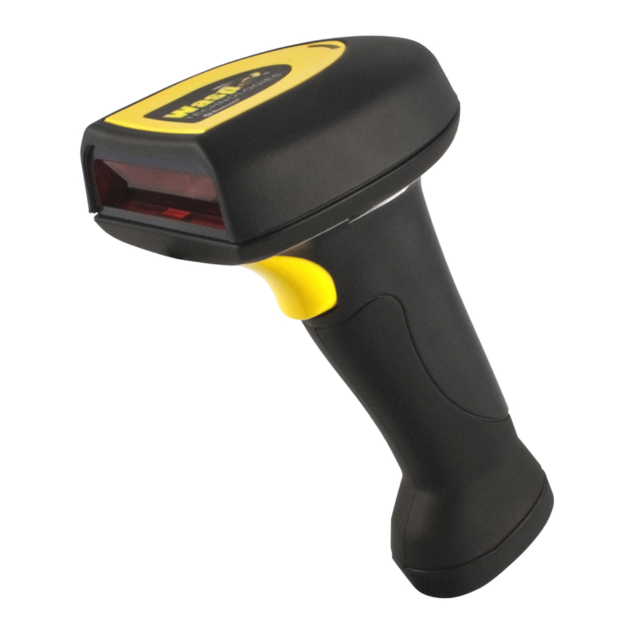
Wasp WWS800 User Manual
Bluetooth wireless scanners
Hide thumbs
Also See for WWS800:
- User manual (30 pages) ,
- Reference manual (27 pages) ,
- Setup instructions (2 pages)
Table of Contents
Advertisement
Quick Links
WARNING
This equipment has been tested and found to comply with the limits for a Class A
digital device, pursuant to Part 15 of FCC Rules. These limits are designed to
provide reasonable protection against harmful interference in a residential
installation. This equipment generates, uses and can radiate radio frequency energy
WWS800/850 Bluetooth Wireless Scanners
and, if not installed and used in accordance with the instructions, may cause
harmful interference to radio communications. However, there is no guarantee that
interference will not occur in a particular installation. If this equipment does cause
harmful interference to radio or television reception, which can be determined by
User's Manual
turning the equipment off and on, the user is encouraged to try correct the
interference by one or more of the following measures:
• Reorient or relocate the receiving antenna.
• Increase the separation between the equipment and receiver.
• Connect the equipment into an outlet on a circuit different from that to which the
receiver is connected.
• Consult the dealer or an experienced radio/TV technician for help.
If applicable, as below
FCC Caution: To assure continued compliance, (example – use only shielded
interface cables when connecting to computer or peripheral devices). Any changes
or modifications not expressly approved by the party responsible for compliance
could void the user's authority to operate this equipment.
This transmitter must not be co-located or operating in conjunction with any other
antenna or transmitter.
FCC Radiation Exposure Statement
This equipment complies with FCC radiation exposure limits set forth for an
uncontrolled environment. This equipment should be installed and operated with
minimum distance 20 cm between the radiator & your body.
This device complies with Part 15 of the FCC Rules. Operation is subject to the
following two conditions: (1) This device may not cause harmful interference, and
(2) this device must accept any interference received, including interference that
may cause undesired operation.
Advertisement
Table of Contents

Related Manuals for Wasp WWS800


Summary of Contents for Wasp WWS800
- Page 1 This equipment generates, uses and can radiate radio frequency energy WWS800/850 Bluetooth Wireless Scanners and, if not installed and used in accordance with the instructions, may cause harmful interference to radio communications. However, there is no guarantee that interference will not occur in a particular installation.
-
Page 2: Table Of Contents
4.4.3 Clear Data ... 13 4.4.4 Send Data... 13 4.4.5 Memory Data Delay... 13 BLUETOOTH SERIAL PORT... 14 WWS800/850 ... 14 ONFIGURING 5.1.1 Activate Bluetooth Serial Port Interface... 14 5.1.2 Authentication & PIN Code ... 14 5.1.3 Device Name Broadcasting ... 14 5.1.4... - Page 3 EQUENCE ...33 ND OF ORMAT ROGRAMMING ...33 CTIVATE DITING ORMATS 9.10 ...34 XCLUSIVE DITING 9.11 ...34 ROGRAMMING XAMPLES CONFIGURING YOUR WWS800/850 ...35 10.1 ...35 NTER ONFIGURATION 10.2 ...35 EFAULT 10.3 ...35 ETTING 10.4 ...36 ETTING ARAMETER ALUES 10.4.1 Numeric Parameters ...36 10.4.2...
-
Page 4: Introduction
1. Introduction This manual described how to operate and configure the WWS800/850 Wireless Barcode Scanner and is divided into two sections. The first section describes the installation, operation and programmable features of the scanner. The second section contains the setup barcodes used to configure the scanner. -
Page 5: Power U P The 2.3 Setup Rf Connection
2.2 Power Up the WWS800/850 When you receive your WWS800/850, the battery will be packaged separately. Please insert the battery into the bottom of the scanner and lock the battery into place by pushing up on the clip. The scanner will beep and the LED will be light up when the device is powered on. -
Page 6: Dc Jack
2.4.3 DC Jack Insert the power supply to the DC Jack at bottom of the scanner. When charging, the scanner LED will flash RED. When the battery is fully charged, around 4 hours from completely empty battery, the LED stays on solid RED. 2.5 Interface Setting Once you have “paired”... -
Page 7: Auto-Sense
Continuous mode for switch-less scanners. 3.4 Auto-Sense Auto-Sense is for WWS800 only and used in conjunction with the auto-sense stand. It will enable the scanner to start scanning once a barcode is brought within Range of the scanner. This will activate the LEDs and the scanner will start decoding the barcode. -
Page 8: Negative Barcodes
4. Output Interface (Base Unit) The WWS800/850 is a multi-interface scanner. It can be used as a keyboard wedge scanner, an RS-232 scanner, or a USB scanner. The output interface can be programmed using the setup barcodes in this manual. -
Page 9: Capital Lock Status
A USB interface is also available. For installation instructions please refer to the separate diskette included with your scanner. 4.4 Memory Parameters The WWS800/850 reserves 4 KB flash memory as transmit buffer when the scanner is out of service range. Data will be saved into the reserved buffer when... -
Page 10: Transmit Buffer Setting
The WWS800/850 can work offline and store the reading data into the internal Flash memory for later upload to the host. The stored data can be up to 128Kbytes. -
Page 11: Update Settings
Before starting the configuration, the scanner must be powered up. If you have not done so, please follow the procedures described in section 2.2 “Power Up the WWS800/850” to power up the scanner. First step of the configuration is always to put the scanner in configuration mode by scanning the “Enter Setup”... -
Page 12: Reset Connection
6.1.2 Reset Connection Scan the “Reset Connection” when switch connection from one PC to another PC. The scanner will re-start itself after this barcode is read. 6.1.3 Authentication & PIN Code The 800/850 scanner can do connection authentication if communication security is desired. -
Page 13: Windows Xp With Service Pack2
6.3 Configuring Bluetooth Device Driver Please follow the procedures below to configure the Bluetooth driver on the host system. Please note that, when searching nearby Bluetooth devices on Host computers, the 800/850 scanner will come out with the serial number as their device name. -
Page 14: Widcomm Bluetooth Driver
8. The scanner is ready to use. Please click OK button. 6.3.2 Widcomm Bluetooth Driver 1. Click icon at PC. 2. Click Find Bluetooth Devices icon at My Bluetooth Places. 3. Right click the 800/850 scanner and select Pair Device. 4. -
Page 15: I Taly / F Rench P Harmacode
6. Click PC Remote Commander icon. 7. Click Yes Button. 8. When the green arrow icon is displayed, the connection is ready. 7. Symbology Parameters This section describes user configurable parameters that are pertaining to barcode symbologies. 7.1 Code39 • Standard / Full ASCII Code 39: User can choose to read either Standard Code 39 or Full ASCII Code 39 by configuring this parameter. -
Page 16: C Odabar
• Checksum Transmission: This parameter specifies whether the checksum character is included in the data being transmitted. • Code Length Qualification: Because of the weak structure of the 2 of 5 codes, a partial scan has a high probability of decoding as a valid but shorter 2 of 5 codes (known as short scan). -
Page 17: P Lessey
• Checksum Verification: Three kinds of checksum calculations can be implemented into MSI code: Single Modulo 10, Double Modulo 10, or Modulo 11 & 10 checksum. If the checksum character is incorrect, the barcode will not be read. • Checksum Transmission: User can control the checksum transmit ion format by configuring this parameter. -
Page 18: Matrix 25
8. Data Output Format Data read by the scanner will be processed in the following sequence (RS-232, Keyboard Wedge and USB interfaces). 1) The character substitution is performed on the barcode data. 2) The Code ID and the Length Code are inserted at the beginning of the data as shown below. -
Page 19: Data Editing
9. Data Editing The WWS800/850 scanner provides advanced data editing functions for data formatting. Data editing is performed according to user configured editing formats. Up to three editing formats can be configured. Data is divided into fields by user specified rules. These fields together with user configurable additional fields constitute the data actually sent to the host computer. -
Page 20: Additional Fields
always included in the field. User though, has the option of discarding this terminating string. • Field Length: The field division can be simply specified by the field length. The scanner will assign the next specified number of characters into the field. -
Page 21: Configuring Your Wws800/850
10. Configuring your WWS800/850 The configuration of WWS800/850 Scanner is done by reading the setup labels contained in the Configuration Manual (the second part of this manual). This section describes the procedure of configuring the scanner. Some configuration examples are also given in this section for illustration. -
Page 22: Key Type/Status Setting
used. These parameters are: Prefix Code, Postfix Code, Code ID, and Additional Fields of Editing Formats. The available key type/status settings can be selected will be described briefly. The configuration procedures for character string parameters are shown below. Parameter Label Key Type / Status Label Two Hexadecimal Labels "Validate"...