Advertisement
Available languages
Available languages
Quick Links
3
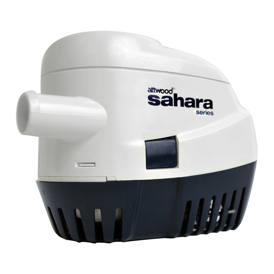
®
Sahara Series Automatic
Bilge Pumps
4505 / 4507 / 4511 Installation Instructions
SAVE THESE INSTRUCTIONS
Form Number 69370 Rev. C
This product carries the standard Attwood three-year warranty.
See www.attwoodmarine.com or Product Catalog for details.
CAUTION:
Read all instructions carefully before installing and using this product.
This pump is sealed and, therefore, submersible. However, the
electrical wire connections must not be submerged. For extra
protection, coat the butt joints and adjacent wire ends liberally with
liquid electrical tape such as MDR
Specifications
ABYC Specifications
13.6-volts DC
(GPH=Gallons Per Hour)
0 ft.
3.3 ft.
Head
Head
Part
Amp GPH/
GPH/
Num. Model Fuse amps
amps
4505
S500
2.0
500/1.5
350/1.4
4507
S750
5.0
750/3.0
625/2.8
4511
S1100 6.0
1100/4.0
970/3.8
WARNING: To prevent injury, always disconnect the power
source when installing or servicing any electrical product.
DO NOT use pump to remove gasoline, oil or other flammable liquids.
Always use the fuse amperage rating specified for your pump model.
Failure to do so could result in serious personal injury or fire hazards.
Attwood bilge pumps are designed to exhaust STANDING WATER
ONLY. They are not intended to prevent rapid accumulation of
on-board water due to rough weather, hull damage, and/or other
unsafe navigational conditions.
REQUIRED MATERIALS
• Hose and thru-hull fittings, available separately from Attwood:
Sahara Model 4505 and 4507–
3/4" I.D. hose: Attwood No. 4199 (includes 2 clamps)
3/4" I.D. thru-hull: No. 3873 (straight), No. 66541 or 66547
(stainless steel straight), No. 3877 (90 ), or No. 3878 (double-end)
Sahara Model 4511–
1-1/8" I.D. hose: No. 11551 (clamps not included)
1-1/8" I.D. thru-hull: No. 3874 (white), No. 3874A (black) or
No. 66543, 66549 (stainless steel), or No. 3879 (90 )
• Two (2) hose clamps suitable for (3/4" or 1-1/8") hose.
• AUTO/OFF/MANUAL dash-mounted control switch
(Attwood No. 7615A).
• In-line fuse connector (Attwood No. 14341) and appropriate
size fuse.
• Three (3) stainless steel #6 x 1/2" self-tapping screws, round
or pan head. Use a #32 drill bit for pilot holes.
• Four (4) wire butt-connectors for 16-gauge wire.
• Two (2) insulated spade terminal connectors for 16-gauge wire.
• Suitable means to make electrical connections waterproof.
• Cordless drill.
• Screwdriver.
03-10
®
or Starbrite
®
.
ISO Specifications
12.0-volts DC
(LPH=Liters Per Hour)
6.7 ft.
10kPa
20kPa
Head
Head
Head
Max Head
GPH/
LPH/
LPH/
(ft.@13.6v/
amps
amps
amps
kPa@12v)
200/1.4 1136/1.2
598/1.2
9'/24
450/2.8 1817/2.5
1306/2.5 16'/36
750/3.8 3104/3.3
2328/3.3 11'7"/28
OPTIONAL MATERIALS
• 1/2"-thick marine plywood block (slightly larger than pump base).
• Waterproof adhesive (epoxy, silicone adhesive, or fiberglass
resin) to mount block.
• 16-gauge wire (brown and black).
PUMP MOUNTING INSTRUCTIONS
WARNING: Remove the pump mounting base (See Figure 3).
Remove the foam block that supports the float during shipping.
Failure to do this prevents the pump from starting when water
is present.
1. Make sure the hull thickness is at least 1/2" thick. If not, place a
block of 1/2" marine plywood (slightly larger than pump base) in
the lowest part of the bilge. Be sure that the pump cover can be
removed for cleaning in this position. Glue the plywood to the
hull with a waterproof adhesive (epoxy, silicone adhesive, or
fiberglass resin). See Figure 1.
Figure 1
Float End
Pump Outlet
Of Pump
Pointing To Transom
Toward Bow
1/2" Thick
Mounting Block
2. Position the pump in the lowest part of the bilge on a flat, level
surface (on the plywood block if it has been installed) with the
outlet pointing toward the transom.
3. Be sure outlet nozzle is level. If pointed upward or downward,
an airlock may form in the pump. (See Figure 1.)
4. The float end of the pump must be level with or above the
pump end (See Figure 1). This prevents the pump from running
out of water while the float is still high enough to activate the pump.
5. Mark location of the three (3) mounting holes with a pencil
or scribe.
WARNING: When drilling holes do not drill through the hull!
6. Carefully drill two 1/8" diameter pilot holes in marked area and
drive a screw in each hole.
7. Slide hose clamps (one to clamp hose to the pump, the other for
the thru-hull connector) over end of the hose. Force hose over
the discharge nozzle of the pump. Install clamp.
8. Route hose on an upward incline to the thru-hull connector.
Avoid dips in hose that can trap water and airlock the pump.
Avoid putting excess tension on hose, which can damage the
pump outlet.
9. Force the hose over the thru-hull barbs and clamp into place.
THRU-HULL CONNECTOR INSTRUCTIONS
If no thru-hull connector exists, choose a location for the fitting.
1. Position thru-hull fittings at least 12" above the water line to
prevent water from coming back into the hull. On sailboats,
mount the thru-hull high enough on the center of the transom
to be above the water line at all times.
2. Place fitting, if possible, on the same side as the steering wheel
so the driver can see discharge of water when the pump is
working properly.
3. Drill hole to match outside diameter of the thru-hull
connector thread.
4. Place a small bead of suitable marine sealant around inside
of the thru-hull connector flange.
Transom
Level
Parallel To
Bottom Of Boat
Advertisement

Related Manuals for Attwood Sahara 4505-1

Summary of Contents for Attwood Sahara 4505-1
- Page 1 ® Sahara Series Automatic Bilge Pumps 4505 / 4507 / 4511 Installation Instructions SAVE THESE INSTRUCTIONS Form Number 69370 Rev. C This product carries the standard Attwood three-year warranty. See www.attwoodmarine.com or Product Catalog for details. CAUTION: Read all instructions carefully before installing and using this product. This pump is sealed and, therefore, submersible.
- Page 2 WARNING: Do not allow sealants containing acetic acid (smells like vinegar) such as silicone rubber sealant to contact the plastic pump housing or thru-hull connector. Such sealants can attack the plastic, causing the pump housing to crack, resulting in pump failure. 5.
- Page 3 ® Pompes d’assèchement automatique de série Sahara 4505 / 4507 / 4511 Directives d’installation CONSERVEZ CES DIRECTIVES Formulaire 69370 Rev. C Ce produit est accompagné de la garantie normale de trois ans de d’Attwood. Pour plus de détails ou pour consulter le catalogue de produits, visitez le www.attwoodmarine.com AVERTISSEMENT: Lisez ces directives attentivement avant d’installer et d’utiliser...
- Page 4 2. Si possible, placez le raccord du même côté que le volant de direction afin que le pilote puisse voir que l’eau s’élimine convenablement une fois la pompe en marche. 3. Forez un trou équivalant au diamètre extérieur du filetage du raccord passe-coque.