Table of Contents
Advertisement
Available languages
Available languages
Safe Operation Practices • Set-Up • Operation • Maintenance • Service • Troubleshooting • Warranty
O
'
M
peratOr
s
anual
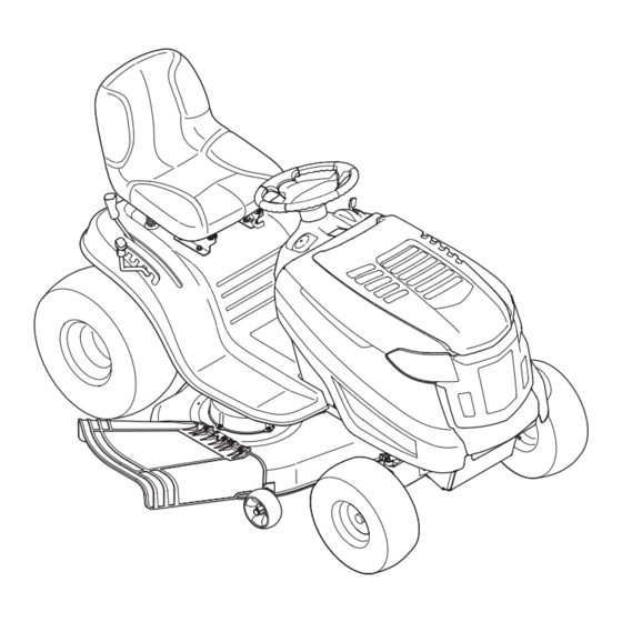
Hydrostatic Lawn Tractor — Horse
WARNING
READ AND FOLLOW ALL SAFETY RULES AND INSTRUCTIONS IN THIS MANUAL
BEFORE ATTEMPTING TO OPERATE THIS MACHINE.
FAILURE TO COMPLY WITH THESE INSTRUCTIONS MAY RESULT IN PERSONAL INJURY.
TROY-BILT, P.O. BOX 361131 CLEVELAND, OHIO 44136-0019
Printed In USA
Form No. 769-06304
(November 1, 2010)
Advertisement
Chapters
Table of Contents

Related Manuals for Troy-Bilt HYDROSTATIC LAWN TRACTOR - HORSE 769-06304


Summary of Contents for Troy-Bilt HYDROSTATIC LAWN TRACTOR - HORSE 769-06304
- Page 1 READ AND FOLLOW ALL SAFETY RULES AND INSTRUCTIONS IN THIS MANUAL BEFORE ATTEMPTING TO OPERATE THIS MACHINE. FAILURE TO COMPLY WITH THESE INSTRUCTIONS MAY RESULT IN PERSONAL INJURY. TROY-BILT, P.O. BOX 361131 CLEVELAND, OHIO 44136-0019 Printed In USA Form No. 769-06304...
-
Page 2: Table Of Contents
Call a Customer Support Representative at (800) 828-5500 or (330) 558-7220 ◊ Write us at Troy-Bilt • P.O. Box 361131 • Cleveland, OH • 44136-0019 If you have any problems or questions concerning the machine, phone a authorized Troy-Bilt service dealer or contact us directly. -
Page 3: Safe Operation Practices
Important Safe Operation Practices WARNING! This symbol points out important safety instructions which, if not followed, could endanger the personal safety and/or property of yourself and others. Read and follow all instructions in this manual before attempting to operate this machine. Failure to comply with these instructions may result in personal injury. - Page 4 A missing or damaged discharge cover can cause blade contact or thrown object injuries. Stop the blade(s) when crossing gravel drives, walks, or roads and while not cutting grass. Watch for traffic when operating near or crossing roadways. This machine is not intended for use on any public roadway.
- Page 5 Children Tragic accidents can occur if the operator is not alert to the presence of children. Children are often attracted to the machine and the mowing activity. They do not understand the dangers. Never assume that children will remain where you last saw them.
-
Page 6: Spark Arrestor
Periodically check to make sure the blades come to complete stop within approximately (5) five seconds after operating the blade disengagement control. If the blades do not stop within the this time frame, your machine should be serviced professionally by an authorized MTD Service Dealer. -
Page 7: Safety Symbols
Safety Symbols This page depicts and describes safety symbols that may appear on this product. Read, understand, and follow all instructions on the machine before attempting to assemble and operate. Symbol READ THE OPERATOR’S MANUAL(S) Read, understand, and follow all instructions in the manual(s) before attempting to assemble and operate DANGER—... - Page 8 2 — i ectiOn MpOrtant peratiOn ractices...
-
Page 9: Assembly & Set-Up
Assembly & Set-Up Assembly & Set-Up Tractor Set-Up Connecting the Battery Cables CALIFORNIA PROPOSITION 65 WARNING Battery posts, terminals, and related accessories contain lead and lead compounds, chemicals known to the State of California to cause cancer and reproductive harm. Wash hands after handling. CAUTION: When attaching battery cables, always connect the POSITIVE (Red) wire to its terminal first,... - Page 10 Attaching The Steering Wheel If the steering wheel for your tractor did not come attached, the hardware for attaching it has been packed within the steering wheel, beneath the steering wheel cap. Carefully pry off the steering wheel cap and remove the hardware. With the wheels of the tractor pointing straight forward, place the steering wheel over the steering shaft.
- Page 11 Tire Pressure WARNING! Maximum tire pressure under any circumstances is 30 psi. Equal tire pressure should be maintained at all times. Never exceed the maximum inflation pressure shown on the sidewall of the tire. The recommended operating tire pressure is: •...
-
Page 12: Controls & Features
Controls and Features Throttle/Choke Lever Ammeter Brake Pedal Parking Brake Lever Ignition Switch Module Speed Control Lever Cup Holder Deck Lift Lever PTO (Blade Engage) Lever Figure 4-1 Lawn Tractor controls and features are illustrated in Fig 4-1 and described on the following pages. WARNING! Read and follow all safety rules and instructions in this manual, including the entire Operation section, before attempting to operate this machine. -
Page 13: Throttle Control Lever
Throttle Control Lever The throttle control lever is located on the right side of the tractor’s dash panel. This lever controls the speed of the engine and, when pushed all the way forward, the choke control also. When set in a given position, the throttle will maintain a uniform engine speed. - Page 14 Parking Brake Pedal and Lever The parking brake pedal is located on the left side running board of the lawn tractor. It is used to both set the parking brake and to stop the lawn tractor in sudden situations. The parking brake lever is located on the left side of the tractor’s dash panel.
-
Page 15: Operation
Operation Operation Safety Interlock Switches This tractor is equipped with a safety interlock system for the protection of the operator. If the interlock system should ever malfunction, do not operate the tractor. Contact an authorized Troybilt service dealer. • The safety interlock system prevents the engine from cranking or starting unless the parking brake is engaged, and the PTO (blade engage) lever is in the disengaged (OFF) position. -
Page 16: Engaging The Parking Brake
Engaging the Parking Brake. To engage the parking brake: Fully depress the brake pedal and hold it down with your foot. Move the parking brake lever all the way down and into the ON position. Release the brake pedal to allow the parking brake to engage. -
Page 17: Engaging The Blades
Driving On Slopes Refer to the SLOPE GAUGE in the Safe Operation section to help determine slopes where you may operate the tractor safely. WARNING! Do not mow on inclines with a slope in excess of 15 degrees (a rise of approximately 2-1/2 feet every 10 feet). - Page 18 Moving The Tractor Manually Your tractor’s transmission is equipped with a hydrostatic relief valve for occasions when it is necessary to move the tractor manually. Activating this valve forces the fluid in the transmission to bypass its normal route, allowing the rear tires to “freewheel.” To engage the hydrostatic relief valve, proceed as follows: Locate the hydrostatic bypass rod in the rear of the tractor.
-
Page 19: Maintenance & Adjustment
Maintenance & Adjustments Maintenance WARNING! Before performing any maintenance or repairs, disengage PTO, move shift lever into neutral position, set parking brake, stop engine and remove key to prevent unintended starting. Engine Refer to the Engine Operator/Owner Manual for engine maintenance instructions. - Page 20 Battery The battery is sealed and is maintenance-free. Acid levels cannot be checked. • Always keep the battery cables and terminals clean and free of corrosive build-up. • After cleaning the battery and terminals, apply a light coat of petroleum jelly or grease to both terminals. •...
-
Page 21: Seat Adjustment
Front To Rear The front of the cutting deck is supported by a stabilizer bar that can be adjusted to level the deck from front to rear. The front of the deck should be between ¼-inch and 3⁄8-inch lower than the rear of the deck. -
Page 22: Maintenance Schedule
Maintenance Schedule Clean Hood/Dash Louvers Check Engine Oil Level Check Air Filter for Dirty, Loose or Damaged Parts Clean and Re-oil Air Filter’s Foam Pre-cleaner Replace Air Filter Element Change Engine Oil and Replace Oil Filter Clean Battery Terminals Lube Front Axles and Rims Clean Engine Cooling Fins Lube Pedal Pivot Points Check Spark Plug Condition &... -
Page 23: Service
Service Service Cutting Deck Removal To remove the cutting deck, proceed as follows: Place the PTO (Blade Engage) lever in the disengaged (OFF) position and engage the parking brake. Lower the deck by moving the deck lift lever into the bottom notch on the right fender. -
Page 24: Cutting Blades
Carefully remove the PTO cable from the rear of the cutting deck by removing the hair pin clip which secures it. Remove the spring from the deck idler bracket. See Fig. 7-4. Figure 7-4 Gently slide the cutting deck (from the left side) out from underneath the tractor. -
Page 25: Changing The Deck Belt
The blades may be removed as follows. Remove the deck from beneath the tractor, Deck Removal earlier in this section) then gently flip the deck over to expose its underside. Place a block of wood between the center deck housing baffle and the cutting blade to act as a stabilizer. - Page 26 To place the new belt, begin by routing the belt around the two outer spindle pulleys as shown in Fig. 7-7. Then route the belt around the two deck idler pulleys as shown in Fig. 7-7. Retighten the left idler pulley hex nut loosened earlier. Remount the belt guards removed earlier.
-
Page 27: Troubleshooting
Troubleshooting Problem Engine fails to start PTO/Blade engaged. Spark plug wire disconnected. Fuel tank empty, or stale fuel. Choke not activated. Faulty spark plug. Blocked fuel line. Engine flooded. Parking brake not engaged Throttle control lever not in correct starting position. -
Page 28: Replacement Parts
Replacement Parts Component EPA Phase III * For use on tractors built after January 1, 2011 in compliance with EPA Phase III Provisions. Contact customer support for more information. NOTE: Download a complete Parts Manual free of charge at www.troybilt.com or phone (800) 828-5500 to purchase a Parts Manual. Be sure to have your model number and serial number ready. -
Page 29: Attachments & Accessories
Attachments & Accessories The following attachments and accessories are compatible for the Troy-bilt Lawn Tractor. See the retailer from which you purchased your tractor, an authorized Troy-bilt Service Dealer or phone (800) 828-5500 for information regarding price and availability. CAUTION: This Troy-Bilt Lawn Tractor is NOT designed for use with any type of ground-engaging attachments (e.g. -
Page 30: Ca. Emission Control Statement
FEDERAL and/or CALIFORNIA EMISSION CONTROL WARRANTY STATEMENT MTD Consumer Group Inc, the United States Environmental Protection Agency (EPA), and, for those products certified for sale in the state of California, the California Air Resources Board (CARB) are pleased to explain the emission (evaporative and/or exhaust) control system (ECS) warranty on your outdoor 2006 and later small off-road spark-ignited engine and equipment (outdoor equipment engine) In California, new outdoor equipment engines must be designed, built and equipped to meet the State’s stringent anti-smog standards (in other states, 1997 and later model year equipment must be designed, built, and equipped to meet the U.S. - Page 31 The repair or replacement of any warranted part otherwise eligible for warranty coverage may be excluded from such warranty coverage if MTD Consumer Group Inc demonstrates that the outdoor equipment engine has been abused, neglected, or improperly maintained, and that such abuse, neglect, or improper mainte- nance was the direct cause of the need for repair or replacement of the part.
-
Page 32: Warranty
MANUFACTURER’S LIMITED WARRANTY FOR The limited warranty set forth below is given by Troy-Bilt LLC with respect to new merchandise purchased and used in the United States and/or its territories and possessions, and by MTD Products Limited with respect to new merchandise purchased and used in Canada and/ or its territories and possessions (either entity respectively, “Troy-... -
Page 33: Espanol
Tractor de Césped — Horse ADVERTENCIA LEA Y SIGA TODAS LAS INSTRUCCIONES DE ESTE MANUAL ANTES DE PONER EN FUNCIONAMIENTO ESTA MÁQUINA. SI NO RESPETA ESTAS INSTRUCCIONES PUEDE PROVOCAR LESIONES PERSONALES. TROY-BILT, P.O. BOX 361131 CLEVELAND, OHIO 44136-0019 Impreso en Estados Unidos de América... - Page 34 ◊ Llame al representante de Atención al Cliente al (800) 828-5500 o (330) 558-7220 ◊ Escríbanos a Troy-Bilt LLC • P.O. Box 361131 • Cleveland, OH • 44136-0019 previo aviso y sin generar responsabilidad por obligaciones de ningún tipo. Si tiene algún problema o duda respecto a la máquina, llame a su distribuidor de servicio local Troy-Bilt autorizado o póngase en...
-
Page 35: Medidas Importantes De Seguridad
Medidas importantes de seguridad ADVERTENCIA: importantes de seguridad que se deben respetar para evitar poner en peligro su seguridad personal y/o material y la de otras personas. Lea y siga todas las instrucciones de este manual antes de poner en funcionamiento esta máquina. Si no respeta estas instrucciones puede provocar lesiones personales. - Page 36 Esté atento a la cortadora y a la dirección de la descarga de los aditamentos y no apunte a nadie. Nunca opere la cortadora de césped sin que estén en su lugar apropiado la cubierta de descarga o el colector de recortes de césped. No ponga las manos o los pies cerca de las piezas rotatorias o debajo de la plataforma de corte.
- Page 37 No cambie a transmisión neutral para descender. El exceso de velocidad puede hacer que el operador pierda el control de la máquina, ocasionando lesiones graves e incluso la muerte. No remolque cargas pesadas detrás de los aditamentos (carrito de basura cargado, podadora de rodillos, etc) en pendientes mayores de 5 grados.
- Page 38 Antes de limpiar, reparar o inspeccionar la máquina, compruebe que la(s) cuchilla(s) y todas las partes en movimiento se hayan detenido. Desconecte el cable de la bujía y póngalo haciendo masa contra el motor para evitar que se encienda accidentalmente. Revise periódicamente para asegurarse que las cuchillas se detengan por completo en aproximadamente cinco (5) segundos después de accionar el control de desenganche...
- Page 39 Safety Symbols This page depicts and describes safety symbols that may appear on this product. Read, understand, and follow all instructions on the machine before attempting to assemble and operate. Symbol LEA EL MANUAL(S) DEL OPERADOR leído, entienda, y siga todas las instrucciones en el manual(s) antes de procurar montar y funcionar PELIGRO—...
- Page 40 2 — M ectiOn edidas iMpOrtantes de seguridad...
-
Page 41: Montaje Y Configuración
Montaje y Configuración CONFIGURACIóN DEL TRACTOR NOTA: Este Manual del operador cubre una gama de especificaciones de productos de varios modelos. Las características y funciones incluidas y/o ilustradas en este manual pueden no ser aplicables a todos los modelos. MTD LLC se reserva el derecho de modificar las especificaciones de los productos, los diseños y el equipo sin previo aviso y sin generar responsabilidad por obligaciones de ningún tipo. - Page 42 ¡ADVERTENCIA! La plataforma de la cortadora de césped puede arrojar objetos. En caso de operar la cortadora de césped sin colocar la cubierta de descarga en la posición adecuada para el funcionamiento, podrían producirse graves lesiones personales y/o daños materiales. Instalación del volante Si el volante del tractor no se envía instalado, debajo de la tapa del volante, dentro del mismo, se entregan embalados los...
- Page 43 Presión de los neumáticos ¡ADVERTENCIA! La presión máxima de los neumáticos en cualquier circunstancia es de 30 psi. Se debe mantener una presión uniforme para todos los neumáticos en todo momento. Nunca exceda la presión máxima de inflado que se indica en los laterales de los neumáticos.
-
Page 44: Controles Y Características
Controls and Features Palanca de estrangulador/obturador Amperímetro Pedal de freno/ embrague Alquiler de palanca de freno Módulo del interruptor de encendido Palanca de cambios Titular de la Copa Palanca de elevación de la plataforma Palanca de potencia de arranque (PTO) (enganche de cuchilla) Figura 4-1 Los controles y características del tractor corta césped se ilustran en la Figura 4-1 y se describen en las páginas siguientes. -
Page 45: Pedal De Freno
PALANCA DE CONTROL DEL REGULADOR La palanca de control del estrangulador está ubicada del lado derecho del tablero de instrumentos del tractor. Esta palanca controla la velocidad del motor y, en algunos modelos, cuando se la empuja totalmente hacia adelante, también controla el obturador. Cuando se lo coloca en una posición determinada, el regulador mantiene una velocidad de motor uniforme. - Page 46 De Velocidad La palanca de control de velocidad, situado en el guardabarros izquierdo, le permite regular la dirección de marcha y la velocidad baja del tractor del césped. Para utilizar, suelte el freno de mano y mover la palanca de control de velocidad hacia adelante (para viajar hacia adelante) o hacia atrás (para viajar a la inversa).
-
Page 47: Funcionamiento
Funcionamiento ADVERTENCIA PARA EVITAR LESIONES PERSONALES GRAVES O LA MUERTE • EN LAS PENDIENTES CONDUZCA HACIA ARRIBA Y HACIA ABAJO, NO DE FORMA TRANSVERSAL. • EVITE MANIOBRAS DE GIRO BRUSCAS. • NO OPERE LA UNIDAD EN ÁREAS DONDE PUEDE DERRAPAR O TROPEZAR. - Page 48 Colocación del freno de mano Para colocar el freno de mano: Presione totalmente el pedal del embrague-freno y manténgalo hacia abajo con el pie. Mueva la palanca de control de velocidad totalmente hacia abajo en la posición de freno de mano. Suelte el pedal del embrague-freno para permitir que el freno de mano engrane.
- Page 49 El tractor de césped es llevado a una parada apretando el pedal de freno. Ponga el freno de estacionamiento totalmente deprimente el pedal de freno y mantenerlo presionado mientras coloca la palanca del freno de estacionamiento en la posición ON. Suelte el pedal del freno para que el freno de estacionamiento a participar.
- Page 50 Mover el tractor manual La transmisión de su tractor está equipado con una válvula de alivio hidrostática para las ocasiones cuando es necesario para mover el tractor de forma manual. La activación de esta fuerza a la válvula de líquido en la transmisión de eludir su ruta normal, permitiendo que las llantas traseras a la “rueda libre”.
-
Page 51: Mantenimiento Y Ajustes
Mantenimiento y Ajustes MANTENIMIENTO ¡ADVERTENCIA! Antes de realizar tareas de mantenimiento o reparaciones, desconecte la potencia de arranque (PTO), mueva la palanca de cambios a la posición neutral, coloque el freno de mano, apague el motor y retire la llave, para evitar el encendido accidental del motor. - Page 52 Limpieza del motor y de la plataforma Si se derrama combustible o aceite sobre la máquina, debe limpiarse de inmediato. NO permita que se acumulen desechos alrededor de las aletas de refrigeración del motor ni en ninguna otra parte de la máquina. IMPORTANTE: NO se recomienda el uso de una lavadora de presión para limpiar el tractor.
- Page 53 Localice la contratuerca y la tuerca de seguridad que se encuentran en la parte delantera de la ménsula estabilizadora. Vea la Fig. 6-3. Después de aflojar la contratuerca: Figura 6-3 Apriete la tuerca de seguridad para levantar la parte frontal de la plataforma;...
- Page 54 Calendario de mantenimiento Limpie el capó/los respiraderos Inspeccione el nivel de aceite del motor Controle el filtro de aire para ver si hay piezas sucias, sueltas o dañadas Limpie y vuelva a lubricar el depurador de espuma del filtro de aire Reemplace el elemento del filtro de aire Cambie el aceite del motor y reemplace el filtro de aceite...
-
Page 55: Servicio
Servicio Extracción de la plataforma de corte Para extraer la plataforma de corte, proceda de la siguiente manera: Coloque la toma de fuerza (PTO) (enganche de cuchilla) en la posición OFF (desconectada) y coloque el freno de mano. Baje la plataforma colocando la palanca de elevación de la plataforma dentro de la muesca inferior en el guardabarros derecho. - Page 56 Extraiga con cuidado el cable de la potencia de arranque (PTO) de la parte posterior de la plataforma de corte retirando el pasador de horquilla que lo fija. Retire el resorte del soporte de polea loca de la plataforma. Vea la Fig.
- Page 57 Cuchillas de corte ¡ADVERTENCIA! Antes de extraer la(s) cuchilla(s) para afilarla(s) o reemplazarla(s), asegúrese de apagar el motor, retirar la llave de encendido, desconectar el(los) cable(s) de la bujía y hacer masa contra el motor para impedir el encendido accidental del motor. Proteja sus manos utilizando guantes pesados o un paño para asir la cuchilla de corte.
- Page 58 Hex Washer Screws Spindle Pulley Deck Idler Pulley Figura 7-7 Para colocar la correa nueva, empieza haciendo que el cinturón alrededor de las dos poleas exterior del huso, como se muestra en la figura. 7-7. Luego, la cinta de ruta alrededor de las dos polines poleas de la cubierta como se muestra en la figura.
-
Page 59: Solución De Problemas
Solución de Problemas Problema El motor no arranca La potencia de arranque (PTO)/cuchilla está conectada. Se ha desconectado el cable de la bujía. El depósito de combustible está vacío o el combustible se ha echado a perder. No se ha activado el obturador. La bujía no funciona correctamente. -
Page 60: Piezas De Reemplazo
Piezas de reemplazo Componente EPA Phase III * Para el uso de tractores fabricados después de enero 1 de 2011 en cumplimiento de la EPA Fase III Disposiciones. Póngase en contacto con atención al cliente para más información. NOTE: Descargue un Manual de Partes completo gratuitamente en www.troybilt.com o teléfono (800) 828-5500 para comprar un Manual de Partes. -
Page 61: Aditamentos Y Accesorios
PRECAUCIóN: Este Troy-Bilt Lawn Tractor no está diseñado para su uso con cualquier tipo de terreno adjuntos de participación (por ejemplo, caña o el arado). El uso de este tipo de equipo se anulará la garantía del tractor. -
Page 62: Garantía
DECLARACIÓN FEDERAL y/o DE CALIFORNIA SOBRE GARANTÍAS EN EL CONTROL DE EMISIONES SUS DERECHOS Y OBLIGACIONES EN CUANTO A LA GARANTÍA MTD Consumer Group Inc, la Agencia de Protección Medioambiental de los Estados Unidos (EPA), y para aquellos productos certificados para su venta en el es- tado de California, el Departamento de los Recursos del Aire de California (CARB) se complacen en explicar la garantía que cubre al sistema de control (ECS) de emisiones (evaporativas y/o de escape) de su equipo y motor (motor de equipos de exteriores) de encendido por chispa para todo terreno, pequeño, de exteriores del año 2006 y años posteriores En California, los nuevos motores de equipos de exteriores deben estar diseñados, construidos y equipados para cumplir con las... - Page 63 Durante la totalidad del período de garantía del motor y equipo para todo terreno arriba mencionado, MTD Consumer Group Inc mantendrá un suministro de piezas bajo garantía suficiente para satisfacer la demanda esperada de tales piezas. Cualquier pieza de reemplazo se podrá usar para el cumplimiento del mantenimiento o las reparaciones bajo garantía y se suministrarán sin cargo para el propietario.
- Page 64 Las disposiciones de esta garantía cubren el recurso de reparación única y exclusiva que surge de la venta. Troy-Bilt no se hará responsable de ninguna pérdida o daño incidental o resultante, incluyendo sin limitación, los gastos incurridos para los servicios de mantenimiento del césped, o los gastos de arrendamiento para...