Table of Contents

Related Manuals for Troy-Bilt 52057


Summary of Contents for Troy-Bilt 52057
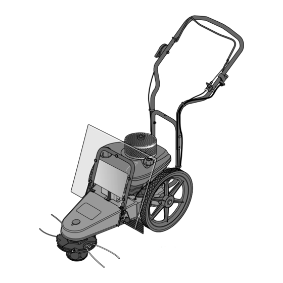
- Page 1 Models 52057 – 5HP Recoil Start 52058 – 6HP Electric Start GARDEN WAY INCORPORATED OWNER’S MANUAL Trimmer/Mower • Safety • Assembly • Features/Controls • Operation • Maintenance • Parts List (Electric Start Model Shown)
-
Page 2: Table Of Contents
Dear Owner: You now own one of the finest trimmer/mowers avail- able. It was designed to easily handle a wide variety of trimming, mowing and clearing chores. You will find the machine to be an invaluable tool in caring for your property. -
Page 3: Section 1: Safety
Section Safety SPARK ARRESTER WARNING TO RESIDENTS OF CALIFORNIA AND SEVERAL OTHER STATES Under California law, and under the laws of several other states, you are not permitted to operate an internal combustion engine using hydrocarbon fuels on any forest covered, brush covered, or grass covered land, or on land covered with grain, hay, or other flammable agricultural crop, without an en- gine spark arrestor in continuous effective working order. -
Page 4: Slope Operation
Section 1: Safety 20. Always wear approved safety gog- gles or safety glasses with side shields when operating equipment. The use of any powered machine can result in for- eign objects being thrown by high- speed rotating parts which can cause personal injury or property damage. -
Page 5: Safety Decals
2. Never run the engine inside a closed area. 3. Never clean, or make adjustments or repairs with the engine running. Disconnect the spark plug wire and keep the wire away from the plug to prevent accidental starting. Remove key on electric start models. 4. -
Page 6: Section 2: Assembly
Section Assembly WARNING To prevent personal injury or property damage, do not attempt to start the engine until all assembly steps are complete and you have read and un- derstand all of the safety and the operating instructions in this Manual. -
Page 7: Step 3: Attach Throttle Control Lever
5. Use two cable ties (F, Figure 2-2) to secure the trimmer head control cable (C) and the electrical wiring har- ness (O) to the handlebar at the loca- tions shown. STEP 3: Attach Throttle Control Lever 1. One end of the Throttle Control Cable (H, Figure 2-3) is attached to the engine. -
Page 8: Step 6: Connect And Charge Battery
Section 2: Assembly STEP 6: Connect and Charge Battery (Electric Start Models) DANGER • Wet conditions can cause an elec- tric shock hazard during battery recharging. Avoid wet conditions when charging battery. • Recharging the battery with im- proper equipment could cause a battery explosion. -
Page 9: Section 3: Features And Controls
Section Features and Controls Operating Symbols Various symbols (shown STOP here, with word descrip- ENGINE tions) are used on the STOP unit. FEATURES AND CONTROLS This Section describes the location and function of the features and controls on your machine. Refer to the following Operation Section for detailed operat- ing instructions. -
Page 10: Section 4: Operation
Section Operation WARNING Before operating your machine, care- fully read and understand all safety (Section 1), controls (Section 3) and operating instructions (Section 4) in this Manual, in the separate Engine Owner’s Manual, and on the decals on the machine. Failure to follow these instructions can result in serious personal injury. -
Page 11: Use The Correct Diameter Trimmer Line
USE THE CORRECT DIAMETER TRIMMER LINE Before starting a project, examine the grass or material you will be cutting and trimming. For tougher conditions, use two (or four) sections of the thicker gauge, .155" diameter extra-heavy duty line. For less demanding conditions, use two sections of the thinner gauge, .130"... -
Page 12: Additional Operating Tips And Techniques
Section 4: Operation WARNING THROWN OBJECT HAZARD • Objects such as rocks, pebbles, and small debris will be thrown violently by the cutting head, resulting in significant hazard to eyes and exposed body parts. • Always wear safety-approved eye protection and suitable clothing and footwear. -
Page 13: Section 5: Maintenance
Section Maintenance WARNING Before inspecting, cleaning or servicing the machine, shut off engine, discon- nect spark plug wire, and make sure that all moving parts have come to a com- plete stop. Remove ignition key on electric start models. Failure to follow these instructions can result in personal injury or property damage. -
Page 14: Removing And Replacing The Trimmer Head
Section 5: Maintenance WARNING Before inspecting, cleaning or servicing the machine, shut off engine, wait for all moving parts to come to a complete stop, disconnect spark plug wire and move wire away from spark plug. Remove ignition key on electric start models. Failure to follow these instructions can result in serious personal injury or property damage. - Page 15 WARNING Before inspecting, cleaning or servicing the machine, shut off engine, wait for all moving parts to come to a complete stop, disconnect spark plug wire and move wire away from spark plug. Remove ignition key on electric start models. Failure to follow these instructions can result in serious personal injury or property damage.
-
Page 16: Cleaning And Debris Removal
Section 5: Maintenance WARNING Before inspecting, cleaning or servicing the machine, shut off engine, wait for all moving parts to come to a complete stop, disconnect spark plug wire and move wire away from spark plug. Remove ignition key on electric start models. Failure to follow these instructions can result in serious personal injury or property damage. -
Page 17: Throttle Control Adjustment
damage caused by overspeeding. Do not tamper with the governor settings. Seek authorized service if you think an adjust- ment is required. Throttle Control Adjustment If the engine does not shut off when the throttle lever is moved to the stop posi- tion, or if the engine does not respond to various throttle settings, refer to the Engine Owner’s Manual for service in-... -
Page 18: Changing Trimming Lines
Section 5: Maintenance WARNING Before inspecting, cleaning or servicing the machine, shut off engine, wait for all moving parts to come to a complete stop, disconnect spark plug wire and move wire away from spark plug. Remove ignition key on electric start models. Failure to follow these instructions can result in serious personal injury or property damage. -
Page 19: Troubleshooting
Before performing any of the corrections in this Troubleshooting Chart, refer to the appropriate information contained in this Manual or the Engine Owner’s Manual for the correct safety precautions and servicing procedures. Contact your local autho- rized Engine Service Dealer for engine service. Contact your local authorized dealer for service problems with the machine. PROBLEM Engine does not start. -
Page 20: Parts List
Parts List Models 52057 & 52058 DRAWING NO. 1... - Page 21 Models 52057 and 52058 Ref. # Part # Description 1917765 Debris Guard ... 1 1918082 Decal-Logo (B) ... 1 1904401 Decal-Logo (A) ... 1 1915290 Push-in Fastener... 5 1917407001 Debris Guard Support... 1 1754128 Hex Flange Screw, 1/4-20 x 3/4 ... 8 1915320 Spacer ...
- Page 22 1917573 1910849 1917746 1917589 1910857 1917572 1910855 1186393 1918332 Models 52057 & 52058 PARTS LIST – DRAWING NO. 2 Description Wheel/Tire Assembly... Locking Retaining Ring ... Flat Washer ... Axle ... Self-Tap Screw, 5/16-18 x 2... Cap Plug... Hex Lock Nut, 1/2-13 ...
- Page 23 Models 52057 and 52058 DRAWING NO. 3 Ref. # 1918283 1915889 1918304 1918070001 1917589 1908677 1749977001 1983658 1185814 1918081 1100807 1110106 1763682 1100799 1917145001 1732499 Ref. # Part # 1904476 1904477 1917598 1768449 N/I Not included with unit, order separately.
-
Page 24: Customer Service Information
CUSTOMER SERVICE INFORMATION Owner Registration Card Please fill out and mail the enclosed owner registration card. The purpose of this card is to register each unit at the factory in order to keep the owner informed with informational bulletins and safety literature. Warranty Service The warranty statement is included in the unit’s literature package.