Tripp Lite UPS SNMPWEBCARD User Manual
Tripp lite ups snmpwebcard user's guide
Hide thumbs
Also See for UPS SNMPWEBCARD:
- Installation manual (45 pages) ,
- Installation instructions manual (20 pages) ,
- User manual (18 pages)
Table of Contents
Advertisement
Quick Links
UPS SNMPWEBCARD
FCC Radio/TV Interference Notice
The SNMPWEBCARD has been tested and found to comply with the limits for a Class A digital device, pursuant to Part 15 of the
FCC Rules. These limits are designed to provide reasonable protection against harmful interference when the equipment is
operated in a domestic environment. Both these devices generate, use and can radiate radio frequency energy and, if not installed
in accordance with the instruction manual, may cause harmful interference to radio communications. The user must use shielded
cables and connectors with these products. Any modifications to these products not expressly approved by the party responsible
for compliance could void the user's authority to operate the equipment.
Technical Support
Call 773-869-1234, Monday—Friday, 8:30 AM—6:00 PM (Central)
Email: techsupport@tripplite.com
This product designed and engineered in the USA.
1111 West 35th Street
Chicago, IL 60609
Customer Support: (773) 869-1234
www.tripplite.com
U
SER
Copyright
All trademarks and trade names are the properties of their respective owners.
'
G
S
UIDE
2005 Tripp Lite. All rights reserved.
i
Advertisement
Table of Contents

Related Manuals for Tripp Lite UPS SNMPWEBCARD


Summary of Contents for Tripp Lite UPS SNMPWEBCARD
-
Page 1: Technical Support
This product designed and engineered in the USA. All trademarks and trade names are the properties of their respective owners. 1111 West 35th Street Chicago, IL 60609 Customer Support: (773) 869-1234 www.tripplite.com ’ UIDE Copyright 2005 Tripp Lite. All rights reserved. -
Page 2: Table Of Contents
TABLE OF CONTENTS Chapter 1: Introduction __________________________________________________________________ 1 System Requirements _________________________________________________________________________ Details - SNMPWEBCARD____________________________________________________________________ Package Contents ____________________________________________________________________________ Chapter 2: Configuration ________________________________________________________________ 4 Selecting an IP Address _______________________________________________________________________ Terminal Mode Configuration _________________________________________________________________ Chapter 3: SNMP_______________________________________________________________________ 5 Chapter 4: Browser Interface _____________________________________________________________ 7 Establishing a Connection______________________________________________________________________________ 7 To Log On to the SNMPWEBCARD _____________________________________________________________________ 7 Navigating the SNMPWEBCARD’s Web Pages ____________________________________________________________ 7... -
Page 3: Chapter 1 Introduction
SNMP protocol and popular SNMP network management platforms such as HP OpenView, IBM NetView, etc., or A Web browser. SNMPWEBCARD System Requirements Tripp Lite UPS with a standard card slot. Ethernet networking environment using the TCP/IP protocol. SNMP-based management station such as:... -
Page 4: Details - Snmpwebcard
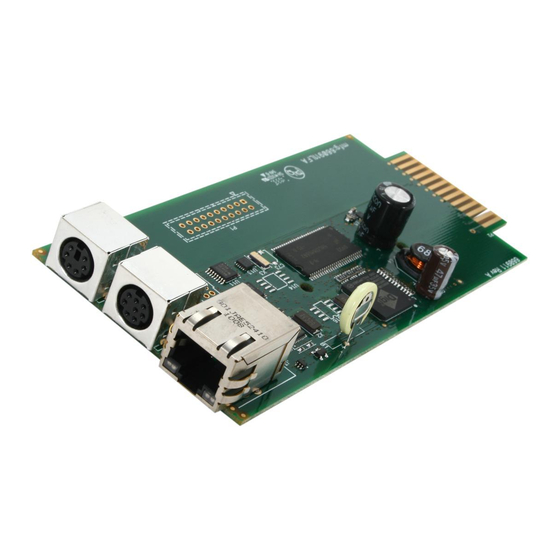
SNMP Adapter User’s Guide SNMPWEBCARD Details Item Description RJ45 Ethernet Connector RJ45 Ethernet Connector with Link & Status LEDs Configuration Port ENVIROSENSE Connector UPS Slot Connector Figure 1-1: SNMPWEBCARD... -
Page 5: Package Contents
SNMP Adapter User’s Guide Package Contents The following items should be included in your package. If any items are missing, contact your dealer immediately: SNMPWEBCARD Installation and Quick Start Guide Configuration Cable CD-ROM Including - MIBs - Owner’s Manual... -
Page 6: Chapter 2: Configuration
Disconnect Ethernet cable and remove the SNMPWEBCARD from the accessory slot. b. Set the SNMPWEBCARD's jumpers. For most Tripp Lite UPS models, set to jumper position 1 (see Fig.1). For models listed below with their corresponding series numbers, set to jumper position 2 (see Fig. 2). Note: Series numbers can be found on the back of the UPS. -
Page 7: Chapter 3: Snmp
Managing the UPS e. Save settings. The card will then reboot; depending on the selected configuration settings, it will take 2-5 minutes for the card to become initialized.* Prepare SNMPWEBCARD for Operation a. Remove the cable connecting the SNMPWEBCARD to the computer. b. -
Page 8: Chapter 3: Snmp
SNMP Adapter User’s Guide Chapter 3 Your SNMPWEBCARD allows a UPS to be managed by SNMP tools, using the UPS SNMP Agent and the UPS SNMP MIB. The UPS SNMP Agent is in the SNMPWEBCARD SNMP firmware. It responds to standard SNMP commands (get, get next and set) and will generate SNMP traps (messages) if configured to do so. -
Page 9: Chapter 4 Browser Interface
Chapter 4 You may monitor and control a UPS system with an SNMPWEBCARD using an Internet browser. The card generates navigable HTML pages. These HTML pages are updated to match UPS status every 30 seconds; the browser will refresh the displayed information automatically. -
Page 10: Status Screen
SNMP Adapter User’s Guide Menu Bar The buttons on the Menu Bar are headings. Clicking on a heading will take you the main page for that menu. If there are sub- menu options, buttons will appear in a frame on the left-hand side of the screen below the menu bar. Clicking on a sub-menu button will make it active. -
Page 11: Action Menu
Troubleshooting Alarm Status The Alarm Status frame monitors connected devices for normal or alarm conditions. This frame will appear at the bottom of every screen, providing a convenient means of notification when alarm conditions occur. (See Figure 4-2.). Figure 4-2: Alarm Status Frame Status—Indicates the severity of the alarm condition. - Page 12 SNMP Adapter User’s Guide Loads The Loads Screen provides a graphical interface to turn on and off any controllable load segment or outlet on a UPS system that supports load management. For each controllable load segment, a representative on/off control will be displayed in the load table. If the UPS does not support individual load control, only one load segment will be displayed.
-
Page 13: Settings Menus
Serial Number—Provides a field for an asset tracking ID number, if required. Low Battery Warning—By default, Tripp Lite UPS Systems signal a low battery warning at 10 percent. Changing this default value to another number provides flexibility in setting actions based on a battery capacity other than the 10 percent. - Page 14 SNMP Adapter User’s Guide Events The Events settings page allows you customize PowerAlert’s response to power events or abnormal conditions on the device. A sample list of events is shown below. Note: Available events vary by device. To select an event, click on it. The available actions for that event will appear on the right side of the screen. No check in the checkbox indicates that the action is turned off.
- Page 15 Troubleshooting Adding an Email Contact—To configure an email address to use when events occur, click on the New button and fill in the information in the pop-up window. Once the SMTP server and at least one email contact have been added, you can send a test email to verify that the settings are correct.
- Page 16 SNMP Adapter User’s Guide Figure 4-8: Configuring SNMP Trap Destinations Network The Settings-Network Menu defines how the SNMPWEBCARD will operate on a network. Please contact you network administrator if there are any questions regarding these settings. (See Figure 4-9.) Figure 4-9: Network Settings Menu...
-
Page 17: Tcp/Ip Menu
Troubleshooting TCP/IP Menu Mac Address—Unique physical address of the SNMPWEBCARD. Boot Mode—Defines how the card will obtain an IP address to run on the network. There are two options: Static: The card must be assigned an address manually. DHCP: The card will request an address from a DHCP server on the network. This is the default setting. If a DHCP server is not available or does not respond to the card’s DHCP request, the card will not be able to access the network. - Page 18 SNMP Adapter User’s Guide System Date/Time—The SNMPWEBCARD has a real-time clock with an onboard battery for backup when the card has been powered down. To set the date/time, enter the correct information and click the Save Change button to write the changes to the card. (See Figure 4-10.) Figure 4-10: Set Date/Time Security—The SNMPWEBCARD has two available levels of security: a guest level (user: guest) allowing read-only access to the...
-
Page 19: Logs
Troubleshooting Event Logs All events are logged to PowerAlert's log database. These event logs may be reviewed by date or by event/category. (See Figure 4-12.) Figure 4-12: Event Logs... -
Page 20: Chapter 5 Troubleshooting
SNMP Adapter User’s Guide Chapter 5 This chapter covers some common problems you may encounter during the configuration and normal operation of the SNMPWEBCARD. Whenever a problem is encountered: Make sure that the SNMPWEBCARD is turned on. Check all connections and make sure they are secure. Refer to the following problems and implement any recommended solutions. -
Page 21: Appendix A: Specifications
Appendix A Memory Power Consumption: Power Input: Size: Ethernet Connector: LEDs: DIP Switches: Temperature/Humidity Connection Operating Temperature: Storage Temperature: Shipping Temperature: Operating Humidity: Storage Humidity: Shipping Humidity: SNMPWEBCARD Intel 80186-25 ROM/RAM: 512Kbytes NVRAM: 2Kbytes < 4 Watts 12 VDC regulated 130mm (L) x 60mm (W) 10 BaseT RJ-45 phone jack PS/2 connector... -
Page 22: Ps/2 Connector
SNMP Adapter User’s Guide PS/2 Connector Serial Port – Adapter Card PS/2 Connector Pins Name Description Ground +9V or Power +12V Not used Not used Serial transmit Serial receive Figure 2:- Pin Assignments Name Description +12V GND +12V +12V Power RXDUPS Connect to UPS Tx signal TXDUPS...