Table of Contents
Advertisement
Available languages
Available languages
1111 W. 35th Street
Chicago, IL 60609 USA
Customer Support: (773) 869-1234
www.tripplite.com
Your PowerVerter Plus converts DC power from connected batteries into AC power for
connected equipment. It can provide up to twice its continuous output rating for short periods,
enabling it to run electrical devices such as motors that have a high power demand at startup.
Read this manual carefully to learn how to connect, operate and maintain your PowerVerter Plus.
Safety:
Installation:
Operation & Features: p. 6 - 7
Service & Warranty:
Specifications:
Diagrams:
Copyright © 2000 Tripp Lite. All rights reserved. PowerVerter
Owner's Manual
PV 500FC
PV 1000FC
PowerVerter Plus
120V, 60 Hz Output
DC-to-AC Power Inverters
• Voltage- and Frequency-Controlled
• High Peak Power, High Efficiency
Español: p. 9
p. 2
p. 8
p. 8
p. 17 - 20
®
is a registered trademark of Tripp Lite.
PV 2000FC
PV 2400FC
®
p. 3 - 5
1
Advertisement
Table of Contents

Related Manuals for Tripp Lite PowerVerter Plus PV 2000FC


Summary of Contents for Tripp Lite PowerVerter Plus PV 2000FC
- Page 1 Read this manual carefully to learn how to connect, operate and maintain your PowerVerter Plus. Safety: Installation: Operation & Features: p. 6 - 7 Service & Warranty: Specifications: Diagrams: Copyright © 2000 Tripp Lite. All rights reserved. PowerVerter Owner's Manual PV 500FC PV 1000FC PowerVerter Plus 120V, 60 Hz Output DC-to-AC Power Inverters •...
- Page 2 Serious injury to property or person could result. Equipment Connection Warnings • Do not use Tripp Lite PowerVerter Systems in life support applications where a malfunction or failure of a Tripp Lite PowerVerter System could cause failure or significantly alter the performance of a life support device.
-
Page 3: Installation Overview
Installation Overview 1) Mount PowerVerter ( Mounting , p. 3) 2) Select Battery(ies) ( Battery Selection , p. 4) 3) Connect Battery(ies) ( Battery Connection , p. 5) 4) Connect Equipment ( Outlets , p. 6) 5) Turn PowerVerter On ( Power Switches , p. 6) Mounting (Optional*) *Recommended for all Vehicular and Marine Applications Due to their size and weight, the PowerVerter Plus systems in this manual should be mounted directly... -
Page 4: Battery Selection
Battery Selection Selecting Battery Type Select a battery or system of batteries that will provide your PowerVerter with proper DC voltage and an adequate amp hour capacity. Select ‘Deep-Cycle’ batteries to enjoy optimum performance from your PowerVerter. Batteries of either Wet-Cell (vented) or Gel-Cell/Absorbed Glass Mat (sealed) construction are ideal. -
Page 5: Battery Connection
1. Connect your PowerVerter's positive DC Terminal directly to a fuse. Tripp Lite strongly recommends that you install a recognized UL component fuse block and fuse within 18 inches of the battery. The fuse's rating must equal or exceed the Minimum DC Fuse Rating listed in your PowerVerter model's specifications on page 8. -
Page 6: Operation & Features
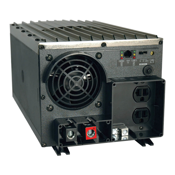
3. REMOTE—OFF—ON Switch (PV 2000FC and PV 2400FC) • Set this 3-position switch to REMOTE to control your PowerVerter at a distance with a Tripp Lite PV/APS Remote (sold seperately). • Move this switch to the ON position to have your PowerVerter provide connected equipment with AC power by converting DC power from an attached battery. -
Page 7: Other Features
9. APS/PV Remote Connector (PV 2000FC and PV 2400FC) This RJ11 jack can be used to connect an optional Tripp Lite APS/PV Remote (sold seperately) to monitor and control the operation of the PowerVerter at a distance. See the instructions packed with the APS/PV Remote for installation, operation and maintenance. -
Page 8: Maintenance And Service
Limited Warranty Tripp Lite warrants its products to be free from defects in materials and workmanship for a period of one year (domestic) or 120 days (export) from the date of initial purchase. Tripp Lite’s obligation under this warranty is limited to repairing or replacing (at its sole option) any such defective products. -
Page 9: Instalación
Características y Operación: p. 14 - 15 Mantenimiento y Servicio: Garantía y Especificaciones: Diagramas: Copyright © 2000 Tripp Lite. Propiedad literaria de Tripp Lite. Reservados todos los derechos. PowerVerter es una marca registrada de Tripp Lite. Manual de Operación PV 500FC PV 1000FC PowerVerter Plus Salida de 120V, 60 Hz Inversores Energía de CD a CA... - Page 10 Advertencias sobre la Conexión de Equipos • No utilice los Sistemas PowerVerter de Tripp Lite en aplicaciones para el soporte de la vida humana donde una falla del Sistema PowerVerter pudiera causar la falla o alterar significativamente el rendimiento del dispositivo de soporte de la vida humana.
- Page 11 Síntesis de Instalación 1. Montaje del PowerVerter (Montaje, página 11) 2. Selección de Batería(s) (Selección de Baterías, página 12) 3. Conexión de Batería(s) (Conexión de Baterías, página 13) 4. Conexión de Equipos (Receptáculos, página 14) 5. Encendido del PowerVerter (Interruptores de Encendido, página 14) Montaje (Opcional*) *Recomendado para aplicaciones marítimas y automovilísticas Debido a su tamaño y peso, los sistemas PowerVerter en este manual deben montarse directamente...
-
Page 12: Selección De Baterías
Selección de Baterías Tipo de Baterías Seleccione una batería o sistema de baterías con capacidad adecuada de voltaje de CD y amperios/ hora para el PowerVerter. Seleccione baterías de “Ciclo Profundo” para obtener rendimiento óptimo del PowerVerter. Las baterías de Celdas Húmedas (ventiladas) o de Celdas de Gel/Fieltro de Vidrio (selladas) son ideales. - Page 13 Tripp Lite recomienda la instalación de una caja de fusibles y un fusible certificado por UL a 18 pulgadas o menos de la batería. El índice del fusible de ser igual o mayor al Indice Mínimo de CD del Fusible como se indica en las especificaciones del PowerVerter en la página 16.
-
Page 14: Luces Indicadoras
Características y Operación (Vea el Diagrama 10, página 20 para obtener información sobre la ubicación de los interruptores, luces indicadoras y otras características) Receptáculos 1. Receptáculos de CA (Todos los modelos) Estos receptáculos de salida suministran energía de CA a los equipos conectados. Los modelos PV 500FC y PV 1000FC incluyen receptáculos tipo NEMA 5-15 y los modelos PV 2000FC y PV 2400FC incluyen receptáculos tipo NEMA 5-20. -
Page 15: Otras Características
9. Conector para “APS/PV Remote” (control remoto para APS/PV) (PV 2000FC y PV 2400FC) Este contacto tipo RJ11 puede utilizarse para conectar un control remoto Tripp Lite opcional de APS/ PV (vendido por separado) y así monitorear y controlar remotamente la operación del PowerVerter. -
Page 16: Garantía Limitada
Garantía Limitada Tripp Lite garantiza que sus productos estarán libres de defectos en materiales y mano de obra por un período de un año (en EE.UU.) o 120 días (fuera de EE.UU.) a partir de la fecha inicial de compra. La obligación de Tripp Lite bajo esta garantía está limitada a reparar o reemplazar (a sola discreción de Tripp Lite) los productos defectuosos. - Page 17 Diagrams/Diagramas Esquemáticos...
- Page 18 Single Battery Vehicular Connection. PV 2000FC or PV 2400FC. See Pg.5. 4.1 is the alternator 4.2 is the vehicle battery ground 4.3 is the vehicle battery 4.4 is the fuse X = Your APS's Inverter's Nominal Input Voltage. (See specifications) Series Battery Vehicular Connection.
- Page 19 Single Battery Vehicular Connection. PV 500FC or PV 1000FC. See Pg.5. 7.1 is the alternator 7.2 is the vehicle battery ground 7.3 is the vehicle battery 7.4 is the fuse X = Your PV's Nominal Input Voltage. (See specifications) Series Battery Vehicular Connection. PV 500FC or PV 1000FC.
- Page 20 A. PV 500FC PV 1000FC B. PV 2000FC PV 2400FC 1. AC Receptacles (All Models) 2. Off–On Switch (PV 500FC and PV 1000FC) 3. Remote–Off–On Switch (PV 2000FC and PV 2400FC) 4. Load Low/Med/High LEDs (All Models) 5. Battery High/Med/Low LEDs (All Models) 6.