Traulsen RBC100 Owner's Manual
Blast chill refrigerators
Hide thumbs
Also See for RBC100:
- Service manual (12 pages) ,
- Training manual (8 pages) ,
- Specifications (2 pages)
Table of Contents
Advertisement
Traulsen & Co., Inc.
OWNER'S MANUAL
Instructions for the installation, operation,
and maintenance of all Blast Chill Models:
This Traulsen unit is built to our highest quality standards. We build our refrigerators, freezers and heated
cabinets this way as a matter of pride. This philosophy has made Traulsen the leader in commercial refrig-
eration since 1938. We thank you for your choice and confidence in Traulsen equipment and we know you
will receive many years of utility from this equipment.
All Traulsen units are placed on a permanent record file with the service department. In the event of any
future questions you may have, please refer to the model and serial number found on the name tag affixed
to the unit. Should you need service, however, call us on our toll free number, 800-825-8220 between 7:30
am and 4:30 pm CST, Monday thru Friday. It is our pleasure to help and assist you in every possible way.
COMPLETE THE FOLLOWING INFORMATION PRIOR TO UNIT INSTALLATION
INITIAL START DATE:
MODEL TYPE:
COMPANY/INDIVIDUAL NAME:
INSTALLER:
RBC DOC REV. 12/02
Quality Refrigeration
Undercounter Model: RBC50
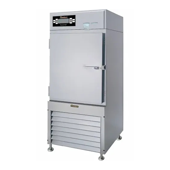
Reach-In Model: RBC100
Roll-In Models: RBC200 & RBC400
Roll-Thru Models: RBC200RT & RBC400RT
INSTALLER
SERIAL NO.
P/N 375-60180-00
Advertisement
Table of Contents

Related Manuals for Traulsen RBC100


Summary of Contents for Traulsen RBC100
- Page 1 All Traulsen units are placed on a permanent record file with the service department. In the event of any future questions you may have, please refer to the model and serial number found on the name tag affixed to the unit.
-
Page 2: Table Of Contents
The serial tag is a permanently affixed sticker on which is recorded vital electrical and refrigeration data about your Traulsen product, as well as the model and serial number. This tag is located inside the door on the right interior wall of the cabinet. -
Page 3: Receipt Inspection
III. d - INSTALLING LEGS OR CASTERS: 6” high stainless steel legs are supplied standard for models RBC50 and RBC100. Casters in lieu of legs are available as an optional accessory for the same models. These are shipped from the factory packed... -
Page 4: E-Cord & Plug
Model RBC100: A minimum of 4” clearance on the right side, 6” on the left side and 6” clearance in the rear (see figure 3). This will allow for sufficient air flow to the refrigeration system and maintenance access. -
Page 5: H-Condensate Removal
Model RBC100 requires a floor drain for condensate removal or the use of a condensate evaporative pan kit (p/n 329-60018-00). The drain port is located at the rear of the unit (see figure 5). -
Page 6: Installing Rbc50 Control Panel
III. l - INSTALLING RBC50 CONTROL PANEL: Model RBC50 is shipped with the control panel de- tached, and laid flat, taped to the cabinet top (see fig- ure 8). This must be installed before use. To install: Remove the packing material and tape holding the control to the top. -
Page 7: Care & Maintenance
IV. a - CLEANING THE CONDENSER: The most important thing you can do to insure a long, reliable service life for your Traulsen is to regularly clean the condenser coil. The self-contained condens- ing unit requires regularly scheduled cleaning to keep the finned condenser clean of lint and dust accumula- tion. -
Page 8: D-Demonstrations
Traulsen 4401 Blue Mound Road Fort Worth, TX 76106 (800) 825-8220 Traulsen & Co., Inc. reserves the right to change speci- fications or discontinue models without notice. V. d - DEMONSTRATIONS: Traulsen sales representatives perform in-service op- erational training for the end-user. Contact the Traulsen Service Department (after completion of the service agency start-up) to arrange this at (800) 825-8220. -
Page 9: D-Maximum Load Per Batch
+61% placed toward the rear of the unit or toward the door. +61% +60% In the RBC100 model, air flows through the unit in a +58% horizontal plane from right to left, therefore, there is +49% no significant difference if the pans are placed toward +47% the rear of the unit or toward the door (see figure 14). -
Page 10: F-Food Probe Placement
VI. BLAST CHILL OPERATION (cont’d) VI. f - FOOD PROBE PLACEMENT: The food probes should be placed into the food prod- uct so that the tip of the probe is near the core (abso- lute center) of the food in the pan. The food probe senses temperature in the last 1”... -
Page 11: H-Example Batches For Rbc100
VI. BLAST CHILL OPERATION (cont’d) VI. h - EXAMPLE BATCHES FOR RBC100: Three food probes are available for assignments of 1, 2 or 3 separate batches of food. They may be assigned in a variety of combinations. Please review some of the various combinations shown in figures 21, 22, 23 &... -
Page 12: I-Example Batches For Roll-In/Roll-Thru Models
VI. BLAST CHILL OPERATION (cont’d) VI. i - EXAMPLE BATCHES FOR ROLL-IN MODELS: Three food probes are available for assignments of 1, 2 or 3 separate batches of food. They may be assigned in a variety of combinations. Please review some of the various combinations shown in figures 25, 26, 27 &... -
Page 13: Operating The Blast Chill Control
VII. OPERATING THE BLAST CHILL CONTROL EMPLOYEE NUMBER PROGRAM A NEW BATCH FOOD PROBES 1,2 & 3 PRODUCT TEMPS PROGRAMMED CHILL CYCLES BLAST CHILL • SOFT CHILL • FLASH CHILL • CONSTANT CHILL • LOCK KEY PAD SETS DATE & TIME VII. -
Page 14: B-Continuous Batching
All batches in pro- cess will complete. VII. e - UNLOCK FUNCTION: Press the hidden button behind the “T” on the Traulsen logo to unlock the lock function. VII. f - DEFROST CYCLE: A. AUTOMATIC DEFROST - will occur every three (3) hours between batches. - Page 15 VII. OPERATING THE BLAST CHILL CONTROL (cont’d) Enter Fig. 30 STEP 3: Notice that the word BLAST is flashing di- rectly above the SOFT/FLASH button. If you wish to blast chill product, press ENTER. If a soft chill is pre- ferred, press the SOFT/FLASH button once, and then press ENTER.
-
Page 16: J-Control Panel Configuration
STEP 1: Start configuration by pressing the “T” on the Traulsen logo (see figure 34). The display will show U1A, which is the maintenance air temperature, 34- °... -
Page 17: K-Probe Temperature & Alarm Warnings
VII. OPERATING THE CONTROL (cont’d) VII. k - PROBE TEMPERATURE & ALARM WARNINGS: The food probes sense temperatures in the last 1” of the probe (nearest the tip). There are three food probe warnings that can occur during a programmed batch. The warnings will flash the “red”... -
Page 18: C-Blast Chill Cycle - Batch Data
VIII. UNDERSTANDING PRINTOUTS (cont’d) VIII. c - BLAST CHILL CYCLE - BATCH DATA: THE BATCH DATA WILL PRINT OUT AUTOMATICALLY AT THE END OF A COMPLETED BATCH Program Chip Revision Operator Number Automatic New Batch Number Unit 1 or 2 Batch Mode: Blast Chill Soft Chill Flash Chill... -
Page 19: D-72-Hour Data Log
VIII. UNDERSTANDING PRINTOUTS (cont’d) VIII. d - THE 72-HOUR DATA LOG: Constant Chill Soft Chill Maintenance Refrigeration Mode Defrost Cycle Blast Chill Alarm Mode Flash Chill PRINTS THE TEMPERATURE IN 5-MINUTE INCREMENTS STARTING WHEN CURRENT DATA WORKING BACK -18- Notes The Time & Date From Power OFF To Power ON Failed Or Un-Plugged Food Probe Chill Cycle Evaporator Coil... -
Page 20: E-Food Probe Failure Warnings
VIII. UNDERSTANDING PRINTOUTS (cont’d) VIII.e - FOOD PROBE FAILURE WARNINGS: FOOD PROBE FAILURE WARNING: Alarm occurs only during a programmed batch. Failed Food Probe Unit Number Location of Failed Probe Alarm Date & Time Employee Number Batch Number CHILL CYCLE BATCH OVER 6 HOURS: Alarm occurs when a programmed batch runs for more than 6 hours. -
Page 21: Trouble Shooting Guide
IX. TROUBLE SHOOTING GUIDE SYMPTOM 1. Condensing unit fails to start when programming a new batch. 2. Batch requires too much time to chill product down to 40° F. “Chill Cycles Batch Over 6-Hours” will ALARM and a printout will note the chill cycle has exceeded maximum safe time. -
Page 22: Wiring Diagrams
X. WIRING DIAGRAM - RBC50 -21-... - Page 23 X. WIRING DIAGRAM - RBC100 -22-...
- Page 24 X. WIRING DIAGRAM - RBC200 & RBC200RT -23-...
-
Page 25: X. Wiring Diagrams
X. WIRING DIAGRAM - RBC400 & RBC400RT -24-... -
Page 26: Warranty Information
(1) year from date of shipment. Under this warranty, TRAULSEN & CO., INC. will reimburse the purchaser for the replacement of any part of said equipment (excluding dryers &... -
Page 27: Parts List
Remote Condensing Units Return Authorization Sealant Solenoid (liquid line) Spindle Unlock Feature Video, Blast Chilling Warranty Wiring Diagram - RBC50 Wiring Diagram - RBC100 Wiring Diagram - RBC200/200RT Wiring Diagram - RBC400/400RT -26- PART # 329-60018-00 333-60082-00 333-60083-00 333-60086-01 333-60086-02... - Page 28 Monday thru Friday 7:30 am - 4:30 pm CST EXTENDED WARRANTY SERVICE HOURS Monday thru Friday 4:30 pm - 6:00 pm CST Quality Refrigeration Traulsen & Co., Inc. 4401 Blue Mound Road Fort Worth, TX 76106 Phone: (800) 825-8220 Fax-Svce: (817) 740-6757 Website: www.traulsen.com...