Table of Contents
Advertisement
Advertisement
Table of Contents

Related Manuals for Toshiba TEC B B-SX5T SERIES


Summary of Contents for Toshiba TEC B B-SX5T SERIES
- Page 1 TEC Thermal Printer B-SX5T SERIES Owner's Manual...
- Page 2 Microsoft is a registered trademark of Microsoft Corporation. Windows is a trademark of Microsoft Corporation. ® As an ENERGY STAR Partner, TOSHIBA TEC has determined that this product meets the ENERGY STAR -- Outline of the International ENERGY STAR The International ENERGY STAR promotes energy saving through the penetration of energy efficient computers and other office equipment.
- Page 3 Do not attempt to effect repairs or modifications to this equipment. If a fault occurs that cannot be rectified using the procedures described in this manual, turn off the power, unplug the machine, then contact your authorised TOSHIBA TEC representative for assistance. This symbol indicates warning items (including cautions).
- Page 4 Request Regarding Maintenance Utilize our maintenance services. After purchasing the machine, contact your authorised TOSHIBA TEC representative for assistance once a year to have the inside of the machine cleaned. Otherwise, dust will build up inside the machines and may cause a fire or a malfunction. Cleaning is particularly effective before humid rainy seasons.
-
Page 5: Table Of Contents
PRODUCT OVERVIEW ...E1-1 Introduction ...E1-1 Features...E1-1 Unpacking ...E1-1 Accessories ...E1-2 Appearance...E1-3 1.5.1 Dimensions ... E1-3 1.5.2 Front View... E1-3 1.5.3 Rear View ... E1-3 1.5.4 Operation Panel... E1-4 1.5.5 Interior... E1-4 PRINTER SETUP...E2-1 Precautions ...E2-1 Procedure before Operation ...E2-2 Fitting the Fan Filter ...E2-2 Connecting the Cables to Your Printer ...E2-3 Connecting the Power Cord ...E2-4 Turning the Printer ON/OFF ...E2-5... - Page 6 CAUTION! 1. This manual may not be copied in whole or in part without prior written permission of TOSHIBA TEC. 2. The contents of this manual may be changed without notification.
-
Page 7: Product Overview
For most queries please refer to this manual and keep it safe for future reference. Please contact your TOSHIBA TEC representative for further information concerning this manual. This printer has the following features: The print head block can be opened providing smooth loading of media and ribbon. -
Page 8: Accessories
1. PRODUCT OVERVIEW Accessories When unpacking the printer, please make sure all the following accessories are supplied with the printer. US Power Cord (1 pc.) (P/No. FBCB0030203) QQ model only CD-ROM (1 pc.) QQ (P/No.: 7FM00332100) QP (P/No.: 7FM00256100) Rewinder Guide Plate (1 pc.) (P/No.: FMBD0034501) Warranty Disclaimer Sheet (1 sheet) QQ-US model only... -
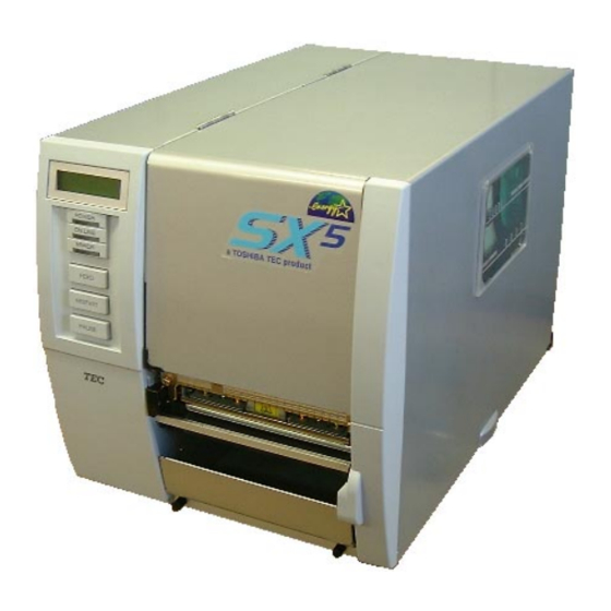
Page 9: Appearance
1. PRODUCT OVERVIEW 1.5 Appearance 1.5.1 Dimensions 1.5.2 Front View 1.5.3 Rear View The names of the parts or units introduced in this section are used in the following chapters. 291 (11.5) LCD Message Display Operation Panel Media Outlet Parallel Interface Connector (Centronics) Serial Interface Connector (RS-232C) -
Page 10: Operation Panel
1. PRODUCT OVERVIEW 1.5.4 Operation Panel 1.5.5 Interior LCD Message Display POWER LED (Green) [FEED] key [RESTART] key Please see Section 3.1 for further information about the Operation Panel. Ribbon Stopper Print Head Block Print Head Platen Head Lever E1- 4 ENGLISH VERSION EO1-33036 1.5 Appearance ON LINE LED... -
Page 11: Printer Setup
For best results, and longer printer life, use only TOSHIBA TEC recommended media and ribbons. Store the media and ribbons in accordance with their specifications. -
Page 12: Procedure Before Operation
2. PRINTER SETUP 2.2 Procedure before Operation NOTE: To communicate with the host computer, one of the following cables is required. (1) RS-232C cable: 25 pins (2) Centronics cable: 36 pins (3) USB: B plug (Option) (4) LAN: 10 Base-T or 100 Base-TX (Option) 2.3 Fitting the Fan Filter This section describes the outline of the printer setup. -
Page 13: Connecting The Cables To Your Printer
2. PRINTER SETUP 2.4 Connecting the Cables to Your Printer NOTES: 1. The picture on the right shows the layout of the interface connectors when the options are fully installed. It may be different depending on your system configuration. 2. The USB interface and LAN interface cannot be used at the same time. -
Page 14: Connecting The Power Cord
2. PRINTER SETUP 2.5 Connecting the Power Cord CAUTION! 1. Make sure that the printer Power Switch is turned to the OFF position ( before connecting the Power Cord to prevent possible electric shock or damage to the printer. 2. Use only the Power Cord supplied with the printer. -
Page 15: Turning The Printer On/Off
2. PRINTER SETUP 2.6 Turning the Printer ON/OFF 2.6.1 Turning ON the Printer CAUTION! Use the power switch to turn the printer On/Off. Plugging or unplugging the Power Cord to turn the printer On/Off may cause fire, an electric shock, or damage to the printer. -
Page 16: Loading The Media
: Labels Position : Tags However, proper position may differ depending on media. For details, refer to TOSHIBA TEC authorised service representative. 3. Do not turn the Locking Ring counter-clockwise too far or it may come off the Supply Holder. - Page 17 2. PRINTER SETUP 2.7 Loading the Media (Cont.) NOTE: Do not over-tighten the Locking Ring of the Supply Holder. Put the media on the Supply Shaft. Pass the media around the Damper, then pull the media towards the front of the printer. Align the projection of the Supply Holder with the groove of the Supply Shaft, and push the Supply Holder against the media until the media is held firmly in place.
- Page 18 2. PRINTER SETUP 2.7 Loading the Media (Cont.) NOTE: Be sure to set the black mark sensor to detect the centre of the black mark, otherwise a paper jam or no paper error may occur. 10. Lower the Print Head Block until it stops. 11.
- Page 19 2. PRINTER SETUP 2.7 Loading the Media (Cont.) NOTES: 1. Be sure to set the Selection Switch to STANDARD/ PEEL OFF position. 2. The backing paper is easier to feed back to the Take-Up Spool if the Front Plate is removed.
- Page 20 2. PRINTER SETUP 2.7 Loading the Media (Cont.) NOTE: Be sure to set the Selection Switch to REWINDER position. ADJUSTMENT: If the media skews when using the Built-in Rewinder, turn the Adjustment Knob of the Rewinder Guide Plate to correct the media feed.
- Page 21 2. PRINTER SETUP 2.7 Loading the Media (Cont.) WARNING! The cutter is sharp, so care must be taken not to injure yourself when handling the cutter. CAUTION! 1. Be sure to cut the backing paper of the label. Cutting labels will cause the glue to stick to the cutter which may affect the cutter quality and...
-
Page 22: Loading The Ribbon
2. PRINTER SETUP 2.8 Loading the Ribbon WARNING! 1. Do not touch any moving parts. To reduce the risk of fingers, jewellery, clothing, etc., being drawn into the moving parts, be sure to load the ribbon once the printer has stopped moving completely. - Page 23 When the auto ribbon saving function is selected, it will be activated to reduce ribbon loss when a no print area extends more than 20 mm. For further information on this function, please ask a TOSHIBA TEC authorised service representative.
-
Page 24: Inserting The Optional Pcmcia Cards
NOTE: Reading a read-only-type flash memory is possible if it has been used on the TOSHIBA TEC printer, such as B-472 and B-572. When the optional PCMCIA Interface Board is installed into the printer, there will be two PCMCIA slots available as shown in the figure below. -
Page 25: Test Print
2. PRINTER SETUP 2.10 Test Print NOTES: 1. Select the sensor type which matches the media being used. Basically, the Reflective Sensor (Black Mark Sensor) is for tag paper, and the Transmissive Sensor (Feed Gap Sensor) is for labels. 2. Select the print mode which matches the media being used. - Page 26 2. PRINTER SETUP 2.10 Test Print (Cont.) NOTE: When PAPER FEED is selected, the printer feeds the media to the correct print start position. If the print start position adjustment is unnecessary, select PAPER NO FEED and save the media. NOTE: If the [FEED] key is pressed after the blank labels are printed, the...
- Page 27 2. PRINTER SETUP 2.10 Test Print (Cont.) 19. When you have finished performing the test print operation, turn the printer’s power OFF then back to ON and check that the LCD Message Display shows ON LINE and that the ON LINE and POWER LED lights are illuminated.
- Page 28 2. PRINTER SETUP ENGLISH VERSION EO1-33036 2.10 Test Print Sample of the bar code test print label 2.10 Test Print (Cont.) Sample of the factory test label E2-18...
-
Page 29: On Line Mode
3. ON LINE MODE 3. ON LINE MODE 3.1 Operation Panel NOTE: Flashes only when the Ribbon Near End Detection function is selected. NOTE: Use the [RESTART] key to resume printing after a pause, or after clearing an error. This chapter describes usage of the keys on the Operation Panel in On Line mode. -
Page 30: Operation
3. ON LINE MODE 3.2 Operation 3.3 Reset NOTE: If the [RESTART] key is held for less than 3 seconds when the printer is in an error or pause state, the printer restarts printing. However, when a communication error or command error occurs, the printer returns to an idle condition. -
Page 31: Dump Mode
In Dump mode, any characters sent from the host computer will be printed. Received characters are expressed in hexadecimal values. This allows the user to verify programming commands and debug the program. For details, please refer to your nearest TOSHIBA TEC service representative. E3- 3 ENGLISH VERSION EO1-33036... -
Page 32: Maintenance
4. MAINTENANCE 4. MAINTENANCE WARNING! 1. Be sure to disconnect the power cord before performing maintenance. Failure to do this may cause an electric shock. 2. To avoid injury, be careful not to pinch your fingers while opening or closing the cover and print head block. -
Page 33: Covers And Panels
4. MAINTENANCE 4.1.1 Print Head/Platen/ Sensors (Cont.) NOTE: Please purchase the Print Head Cleaner (P/No. 24089500013) from your authorised TOSHIBA TEC service representative. 4.1.2 Covers and Panels CAUTION! 1. DO NOT POUR WATER directly onto the printer. 2. DO NOT APPLY cleaner or detergent directly onto any cover or panel. -
Page 34: Optional Cutter Module
4. MAINTENANCE 4.1.3 Optional Cutter Module WARNING! 1. Be sure to turn the power off before cleaning the Cutter Module. 2. As the cutter blade is sharp, care should be taken not to injure yourself when cleaning. 4.2 Care/Handling of the Media and Ribbon CAUTION! Be sure to carefully review... -
Page 35: Troubleshooting
This chapter lists the error messages, possible problems, and their solutions. If a problem cannot be solved by taking the actions described in this chapter, do not attempt to repair the printer. Turn off and unplug the printer, then contact an authorised TOSHIBA TEC service representative for assistance. -
Page 36: Possible Problems
Remove the ribbon, and check the status of the ribbon. Replace the ribbon, if necessary. If the problem is not solved, turn off the printer, and call a TOSHIBA TEC authorised service representative. Load a new ribbon. Then press the [RESTART] key. -
Page 37: Removing Jammed Media
Do not use any tool that may damage the Print Head. NOTE: If you get frequent jams in the cutter, contact a TOSHIBA TEC authorised service representative. This section describes in detail how to remove jammed media from the printer. -
Page 38: Threshold Setting
TOSHIBA TEC service representative. To maintain a constant print position the printer uses the Transmissive Sensor to detect the gap between labels by measuring the amount of light passing through the media. -
Page 39: Appendix 1 Specifications
APPENDIX 1 SPECIFICATIONS APPENDIX 1 SPECIFICATIONS Appendix 1 describes the printer specifications and supplies for use on the B-SX5T printer. A1.1 Printer The following is the printer specifications. Item Supply voltage Power consumption During a print job During standby Operating temperature range Relative humidity Resolution Printing method... -
Page 40: A1.2 Options
TEC Head Quarters. A1.3 Media Please make sure that the media being used is approved by TOSHIBA TEC. The warranty does not apply when a problem is caused by using media that is not approved by TOSHIBA TEC. For information regarding TOSHIBA TEC approved media, please contact a TOSHIBA TEC authorised service representative. -
Page 41: A1.3.2 Detection Area Of The Transmissive Sensor
4. “On the fly issue” means that the printer can feed and print without stopping between labels. 5. There are restrictions in use of the media which is narrower than 50 mm. For details, refer to TOSHIBA TEC service representative . -
Page 42: A1.3.3 Detection Area Of The Reflective Sensor
APPENDIX 1 SPECIFICATIONS A1.3.2 Detection Area of the Transmissive Sensor (Cont.) <Tag paper with square holes> Sensor position Min. 2.0 mm NOTE: Round holes are not acceptable. A1.3.3 Detection Area of the Reflective Sensor The Reflective Sensor is movable from the centre to the left edge of media. The reflection factor of the Black Mark must be 10% or lower with a waveform length of 950 nm. -
Page 43: A1.4 Ribbon
A1.4 Ribbon Please make sure that the ribbon being used is approved by TOSHIBA TEC. The warranty does not apply to any problem caused by using non-approved ribbons. For information regarding TOSHIBA TEC approved ribbon, please contact a TOSHIBA TEC service representative. -
Page 44: Appendix 2 Messages And Leds
APPENDIX 2 MESSAGES AND LEDS APPENDIX 2 MESSAGES AND LEDS Appendix 2 describes the LCD messages displayed on the operation panel. Symbols in the message : The LED is illuminated. 2: ****: the number of unprinted media. Up to 9999 (in pieces) 3: %%%%%%%: ATA Card’s remaining memory 0 to 9999999 (in K bytes) 4: ###: Flash memory card remaining memory for PC save area: 0 to 895 (in K bytes) 5: &&&&: Remaining flash memory capacity for storing writable characters 0 to 3147 (in K bytes) - Page 45 APPENDIX 2 MESSAGES AND LEDS NOTES: If a command error is found in the command received, 16 bytes of the command error, starting from the command code, will be displayed. (However, [LF] and [NUL] will not be displayed.) Example 1 [ESC] T20 G30 [LF] [NUL] Command error The following message appears.
-
Page 46: Appendix 3 Interface
APPENDIX 3 INTERFACE APPENDIX 3 INTERFACE Interface Cables To prevent radiation and reception of electrical noise, the interface cables must meet the following requirements: Fully shielded and fitted with metal or metallised connector housings. Keep as short as possible. Should not be bundled tightly with power cords. Should not be tied to power line conduits. -
Page 47: Appendix 4 Print Samples
APPENDIX 4 PRINT SAMPLES ENGLISH VERSION EO1-33036 APPENDIX 4 PRINT SAMPLES APPENDIX 4 PRINT SAMPLES n Font EA4-1... - Page 48 APPENDIX 4 PRINT SAMPLES APPENDIX 4 PRINT SAMPLES (Cont.) n Bar codes JAN8, EAN8 Interleaved 2 of 5 UPC-E EAN13+5 digits CODE39 (Full ASCII) UPC-E+2 digits EAN8+2 digits UPC-A CODE39 (Standard) JAN13, EAN13 EAN13+2 digits CODE128 CODE93 UPC-E+5 digits EAN8+5 digits UPC-A+2 digits EA4-2 ENGLISH VERSION EO1-33036...
- Page 49 APPENDIX 4 PRINT SAMPLES APPENDIX 4 PRINT SAMPLES (Cont.) UPC-A+5 digits Industrial 2 of 5 Customer bar code KIX Code RSS-14 RSS-14 Stacked Omnidirectional Data Matrix QR code MaxiCode UCC/EAN128 POSTNET Customer bar code of high priority RM4SCC RSS-14 Stacked RSS Limited RSS Expanded PDF417...
- Page 50 GLOSSARIES GLOSSARIES Bar code A code which represents alphanumeric characters by using a series of black and white stripes in different widths. Bar codes are used in various industrial fields: Manufacturing, Libraries, Retail, Transportation, Warehousing, etc. Reading bar codes is a fast and accurate means of capturing data while keyboard entry tends to be slow and inaccurate.
- Page 51 GLOSSARIES Pre-printed media A type of media on which characters, logos, and other designs have been already printed. Print head element The thermal print head consists of a single line of tiny resistive elements and when current is allowed to flow through each element it heats up causing a small dot to be burned onto thermal paper or a small dot of ink to be transferred from a thermal ribbon to ordinary paper.
- Page 52 INDEX INDEX Auto ribbon saving 2-13 Backing paper A1-3 Bar code A1-1 Batch mode 2-9 Black mark 2-8, A1-2, A1-4 Black mark length A1-3 Black mark sensor 2-8, 4-2 Built-in rewinder 2-10 Centronics 1-3, 2-3 Cut mode 2-11 Cutter module 2-11, 4-3, A1-2 Dimensions 1-3 Effective Print length A1-3 Effective print width A1-3...
- Page 53 INDEX ENGLISH VERSION EO1-33036 INDEX Serial interface 1-3 Strip mode 2-9 Strip module 2-9, A1-2 Supply voltage A1-1 Tag A1-2 Test print 2-15 Thermal direct 2-15, A1-1 Thermal transfer 2-15, A1-1 Threshold setting 5-4 Transmissive sensor 2-15, A1-3 Two-dimensional code A1-1 USB interface 1-3, 2-3, A1-2 Weight A1-1...
- Page 56 EO1-33036B...