Toshiba TOSVERT VF-S11 Instruction Manual
Industrial inverter for 3-phase induction motors
Hide thumbs
Also See for TOSVERT VF-S11:
- Instruction manual (269 pages) ,
- Option instruction manual (22 pages) ,
- Specifications (12 pages)
Table of Contents
Advertisement
Industrial Inverter
For 3-phase induction motors
Instruction Manual
TOSVERT
< Simplified manual >
1-phase 240V class 0.2
3-phase 240V class 0.4
3-phase 500V class 0.4
3-phase 600V class 0.75
1.Make sure that this instruction manual is delivered to the
end user of the inverter unit.
2.Read this manual before installing or operating the inverter
unit, and store it in a safe place for reference.
S11
VF-
TM
2.2kW
15kW
15kW
15kW
NOTICE
E6581160
I
Safety
precautions
Contents
1
Read first
2
Connection
3
Operations
4
Basic VF-S11
operations
5
Monitoring the
operation status
6
Measures
to satisfy the
standards
7
Table of
parameters
and data
8
Specifications
9
Before making
a service call
9
Measures
to satisfy the
standards
10
Peripheral
devices
11
Table of
parameters
and data
12
Specifications
13
Before making a service
call - Trip information and
remedies
14
Inspection and
maintenance
15
Warranty
16
Disposal of the
inverter
2004 Ver. 108/109
Advertisement
Table of Contents

Related Manuals for Toshiba TOSVERT VF-S11


Summary of Contents for Toshiba TOSVERT VF-S11
-
Page 1: Industrial Inverter
2.Read this manual before installing or operating the inverter unit, and store it in a safe place for reference. E6581160 Safety precautions Contents Read first Connection Operations Basic VF-S11 operations Monitoring the operation status Measures to satisfy the standards Table of parameters... -
Page 2: I Safety Precautions
Safety precautions The items described in these instructions and on the inverter itself are very important so that you can use the inverter safely, prevent injury to yourself and other people around you as well as to prevent damage to property in the area. -
Page 3: General Operation
General Operation • Never disassemble, modify or repair. This can result in electric shock, fire and injury. For repairs, call your sales distributor. Disassembly prohibited • Never remove the front cover when power is on or open door if enclosed in a cabinet. The unit contains many high voltage parts and contact with them will result in electric shock. - Page 4 Operation cannot be stopped immediately by the inverter alone, thus risking an accident or injury. • All options used must be those specified by Toshiba. The use of any other option may result in an accident.
- Page 5 • Electrical installation work must be done by a qualified expert. Connection of input power by someone who does not have that expert knowledge may result in fire or electric shock. • Connect output terminals (motor side) correctly. If the phase sequence is incorrect, the motor will operate in reverse and that may result in injury. •...
-
Page 6: Maintenance And Inspection
• Observe all permissible operating ranges of motors and mechanical equipment. (Refer to the motor's instruction manual.) Not observing these ranges may result in injury. Prohibited When sequence for restart after a momentary failure is selected (inverter) • Stand clear of motors and mechanical equipment. If the motor stops due to a momentary power failure, the equipment will start suddenly after power recovers. -
Page 7: Table Of Contents
Standard connections ...10 Description of terminals...12 3. Operations ...19 Simplified operation of the VF-S11...19 How to operate the VF-S11 ...23 4. Basic VF-S11 operations...27 Flow of status monitor mode ...28 How to set parameters ...29 5. Monitoring the operation status...36 Status monitor mode ...36... -
Page 8: Read First
1. Read first Thank you for your purchase of the Toshiba “TOSVERT VF-S11” industrial inverter. This manual is a simplified version. If you need a detailed explanation, refer to the full version of English manual (E6581158). This is the Ver. 108 / Ver. 109 CPU version inverter. - Page 9 No part of the contents of the CD-ROM shall be reproduced without written permission from Toshiba Schneider Inverter Corporation. [Exclusions] Toshiba Schneider Inverter Corporation shall have no liability for any damage of any kind caused by the use of this CD- ROM. Warning...
-
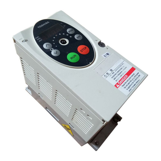
Page 10: Contents Of The Product
Contents of the product Explanation of the name plate label. Always shut power off first then check the ratings label of inverter held in a cabinet. Type V F S 11 S - 2 0 0 7 P L E - W N - A 2 2 Applicable motor Model name Input (AC) voltage... -
Page 11: Connection
*5: 600V models have no noise filter inside. DC reactor (DCL) *2 (option) PA/+ R/L1 S/L2 Noise Power circuit T/L3 filter Control circuit VF-S11 Operation panel Connector for common serial communications SOURCE SINK CC VIA VIB Meter Frequency meter (ammeter) External potentiometer (1~10kΩ) - Page 12 *4: If you are using a 600V model, be sure to connect an input reactor (ACL). *5: 600V models have no noise filter inside. PA/+ PC/- Noise Power circuit filter Control circuit VF-S11 Operation panel Connector for common serial communications SOURCE SINK CC VIA VIB Frequency meter (ammeter) External potentiometer (1~10kΩ)
-
Page 13: Description Of Terminals
Description of terminals 2.2.1 Power circuit terminals In case of the lug connector, cover the lug connector with insulated tube, or use the insulated lug connector. Screw size M3.5 screw M4 screw M5 screw M6 screw Power circuit Terminal symbol R/L1,S/L2,T/L3 U/T1,V/T2,W/T3 PA/+,PB... - Page 14 Capacity of Voltage class applicable Inverter model motor (kW) VFS11-4004PL 0.75 VFS11-4007PL VFS11-4015PL VFS11-4022PL Three-phase VFS11-4037PL 500V class VFS11-4055PL VFS11-4075PL VFS11-4110PL VFS11-4150PL 0.75 VFS11-6007P VFS11-6015P VFS11-6022P Three-phase VFS11-6037P 600V class VFS11-6055P VFS11-6075P VFS11-6110P VFS11-6150P Note 1: Sizes of the wires connected to the input terminals R/L1, S/L2 and T/L3 and the output terminals U/T1, V/T2 and W/T3 when the length of each wire does not exceed 30m.
-
Page 15: Control Circuit Terminals
Control circuit terminals Terminal Input/output symbol Shorting across F-CC causes forward rotation; open causes slow- Input down and stop. (When ST is always Shorting across R-CC causes reverse rotation; open causes slow- Input down and stop. (When ST is always This inverter protective function is disabled if RES are CC is connected. - Page 16 Terminal Input/output symbol Multifunction programmable analog input. Standard default setting: 0~10Vdc input and 0~60Hz (0~50Hz) frequency By changing parameter setting, this Input terminal can also be used as a multifunction programmable contact input terminal. When using the sink logic, be sure to insert a resistor between P24 and VIB.
- Page 17 Terminal Input/output symbol Multifunction programmable relay contact output. Standard default settings detect and Output output low-speed signal output frequencies. Multifunction output terminals to which two different functions can be assigned. SINK (Negative) logic/SOURCE (Positive) logic (When the inverter's internal power supply is used) Current flowing out turns control input terminals on.
- Page 18 SINK (Negative) logic/SOURCE (Positive) logic (When an external power supply is used) The PLC terminal is used to connect to an external power supply or to insulate a terminal from other input or output terminals. As for input terminals, turn the SW1 slide switch to the PLC position. <Examples of connections when an external power supply is used>...
- Page 19 Logic switching/Voltage-current output switching (slide switch) Logic switching Use SW1 to switch between logics. Switch between logics before wiring to the inverter and without supplying power. If switching between sink, source and PLC is done when power is turned on after switching or when the inverter is supplied with power, the inverter might become damaged.
-
Page 20: Operations
3. Operations Simplified Operation of the VF-S11 The procedures for setting operation frequency and the methods of operation can be selected from the following. Start / Stop Setting the frequency Use the basic parameters (Speed setting mode selection). Title Command mode selection... - Page 21 3.1.1 How to start and stop [Example of a Key operated MODE (1) Start and stop using the operation panel keys ( Use the : Motor starts. To switch between forward run and reverse run from the control panel, the parameter fr ✩...
- Page 22 3.1.2 How to set the frequency [Example of a setting procedure] Key operated LED display MODE ⇔ Pressing the MODE key twice returns the display to standard monitor mode (displaying operation frequency). (1) Setting the frequency using the potentiometer on the inverter main unit Set the frequency with the notches on the potentiometer.
-
Page 23: Frequency Setting
(3) Setting the frequency using the operation panel ( Frequency setting Setting the frequency using external potentiometer * The input terminal VIA can be used in the same way. = : VIA effective, Setting the frequency using input voltage (0~10V) * The input terminal VIB can be used in the same way. -
Page 24: How To Operate The Vf-S11
How to operate the VF-S11 Overview of how to operate the inverter with simple examples. Setting the operation frequency using built-in potentiometer and Ex.1 running and stopping using the operation panel. Wiring MCCB Parameter setting (default setting) Title Command mode selection... - Page 25 Ex.2 Wiring Parameter setting Title Operation Run/stop: Press the Frequency setting: Set with the * 600V models have no noise filter inside. Setting the operation frequency using the operation panel and running and stopping using the operation panel. PA/+ MCCB R/L1 S/L2 Noise...
- Page 26 Setting the operation frequency using built-in potentiometer and Ex.3 running and stopping using external signals. Wiring MCCB R/L1 S/L2 Noise T/L3 Parameter setting Title Command mode selection Frequency setting mode selection Operation Run/stop: ON/OFF input to F-CC, R-CC. (Set SW1 to Sink logic) Frequency setting: Set adjusting position of notches on the potentiometer.
- Page 27 Ex.4 Wiring MCCB Parameter setting Title Operation Run/stop: ON/OFF input to F-CC, R-CC. (Set SW1 to Sink logic) Frequency setting: VIA and VIB: 0-10Vdc (External potentiometer) Note) Use the VIA slide switch to switch between voltage and current to the VIA terminal. Voltage input: V side Current input: I side * 600V models have no noise filter inside.
-
Page 28: Basic Vf-S11 Operations
4. Basic VF-S11 operations The VF-S11 has the following four monitor modes. : The standard inverter mode. This mode is enabled when Standard monitor mode This mode is for monitoring the output frequency and setting the frequency designated value. In it is also displayed information about status alarms during running and trips. -
Page 29: Flow Of Status Monitor Mode
E6581160 Flow of status monitor mode Status monitor mode Flow of monitor as following Setting monitor mode MODE MODE Standard monitor mode 28 kinds of data Display mode MODE 10 kinds of data Data of 4 times. Past trip record detained monitor mode Note: To return to the original display mode, press the MODE key. -
Page 30: How To Set Parameters
How to set parameters The standard default parameters are programmed before the unit is shipped from the factory. Parameters can be divided into 4 major categories. Select the parameter to be changed or to be searched and retrieved. Basic parameters Extended parameters User parameters (automatic edit function) - Page 31 4.2.1 How to set the basic parameters All of the basic parameters can be set by the same step procedures. [Steps in key entry for basic parameters] MODE Steps in setting are as follows (example of changing the maximum frequency from 80Hz to 60Hz). Key operated MODE After this,...
- Page 32 4.2.2 How to set extended parameters The VF-S11 has extended parameters to allow you to make full use of its functions. All extended parameters are expressed with Basic parameters Press the MODE key once and use the to select from the basic parameters.
- Page 33 Example of parameter setting Steps in setting are as follows (Example of changing the dynamic braking selection Key operated MODE If there is anything you do not understand during this operation, press the MODE key several times to start over from the step of For details on the function of each parameter, refer to the full version of English manual (E6581158).
- Page 34 Key operated LED display ( ) ↓ ⇔ ( ) MODE ↓ MODE ↓ If there is anything you do not understand during this operation, press the start over from the step of auh display. 4.2.4 Searching for a history of changes, using the history function ( History function ( Automatically searches for 5 latest parameters that are programmed with values different from the...
- Page 35 How to use the history function Key operated MODE MODE MODE MODE Note) Parameter f700 (Prohibition of change of parameter settings) is not displaied in this “auh”. 4.2.5 Parameters that cannot be changed while running For safety reasons, the following parameters have been set up so that they cannot be reprogrammed while the inverter is running.
- Page 36 4.2.6 Returning all parameters to standard default setting Setting the standard default setting parameter default settings. Note: For more details on the standard default setting parameter Notes on operation • We recommend that before this operation you write down on paper the values of those parameters, because when setting factory default setting.
-
Page 37: Monitoring The Operation Status
5. Monitoring the operation status Refer to 4.1 about flow of monitor. Status monitor mode 5.1.1 Status monitor under normal conditions In this mode, you can monitor the operation status of the inverter. To display the operation status during normal operation: Press the MODE Setting procedure (eg. - Page 38 (Continued) Item displayed operated Note 4 Input terminal Note 5 Output terminal CPU1 version CPU2 version Memory version PID feedback Frequency command value (PID-computed) Integral input Note 6 power Integral output Note 6 power Rated current Note 7 Past trip 1 Note 7 Past trip 2 Past trip 3...
- Page 39 (Continued) Item displayed Note 7 Past trip 4 Note 8 Parts replacement alarm information Cumulative Note 9 operation time Default display mode Communic operated display ation No. ⇔ FE13 Past trip 4 (displayed alternately) The ON/OFF status of each of the cooling fan, circuit board capacitor, main circuit capacitor of parts replacement alarm or cumulative operation time are displayed in bits.
-
Page 40: Display Of Detailed Information On A Past Trip
5.1.2 Display of detailed information on a past trip Details on a past trip (of trips 1 to 4) can be displayed, as shown in the table below, by pressing the when the trip record is selected in the status monitor mode. Unlike the "Display of detailed trip information at the occurrence of a trip"... -
Page 41: Display Of Trip Information
Display of trip information 5.2.1 Trip code display If the inverter trips, an error code is displayed to suggest the cause. Since trip records are retained, information on each trip can be displayed anytime in the status monitor mode. For the kinds of causes that can be indicated in the event of a trip, see section 9.1. 5.2.2 Display of trip information at the occurrence of a trip At the occurrence of a trip, the same information as that displayed in the mode described in 5.1.1, "Status monitor... - Page 42 (Continued) Item displayed operated Note 4 Input terminal Note 5 Output terminal CPU1 version CPU2 version Memory version PID feedback Frequency command value (PID-computed) Integral input power Integral output power Rated current Note 7 Past trip 1 Note 7 Past trip 2 Past trip 3 Note 7 Note 7...
- Page 43 (Continued) Item displayed Note 8 Parts replacement alarm information Cumulative Note 9 operation time Default display mode Note 1: Items displayed can be changed by pressing Note 2: You can switch between % and A (ampere)/V (volt), using the parameter selection).
- Page 44 Note 9: The cumulative operation time increments only when the machine is in operation. Note 10: At the occurrence of a trip, maximum values are not always recorded and displayed for reasons of detecting time. Note 11: If there is no trip record, nerr is displayed. Of the items displayed on the monitor, the reference values of items expressed in percent are listed below.
-
Page 45: Measures To Satisfy The Standards
Inverters themselves are not subject to approval for CE marking. The CE mark must be put on every final product that includes an inverter(s) and a motor(s). The VF-S11 series of inverters complies with the EMC directive if an EMI filter recommended by Toshiba is connected to it and wiring is carried out correctly. -
Page 46: Measures To Satisfy The Emc Directive
Category Subcategory Radiation noise Emission Transmission noise Static discharge Radioactive radio-frequency magnetic contactor field First transient burst Immunity Lightning surge Radio-frequency induction/transmission interference Voltage dip/Interruption of power Emission standards other than the above are applied to inverters when used in a commercial environment but not an industrial environment. - Page 47 VFS11S-2015PL VFS11S-2022PL Note : For 600V models compliant with EU standards, contact your nearest Toshiba inverter distributor. Use shielded power cables, such as inverter output cables, and shielded control cables. Route the cables and wires so as to minimize their lengths. Keep a distance between the power cable and the control cable and between the input and output wires of the power cable.
- Page 48 6.1.3 About the low-voltage directive The low-voltage directive provides for the safety of machines and systems. All Toshiba inverters are CE-marked in accordance with the standard EN 50178 specified by the low-voltage directive, and can therefore be installed in machines or systems and imported without problem to European countries.
-
Page 49: Compliance With Ul Standard And Csa Standard
Install a non-fuse circuit breaker or a fuse on the input side of the inverter. Compliance with UL Standard and CSA Standard The VF-S11 models, that conform to the UL Standard and CSA Standard have the UL/CSA mark on the nameplate. - Page 50 AIC, Fuse and Wire sizes Capacity of Voltage applicable motor Inverter model class (kW) VFS11S-2002PL VFS11S-2004PL Single-phase 0.75 VFS11S-2007PL 240V class VFS11S-2015PL VFS11S-2022PL VFS11-2004PM 0.55 VFS11-2005PM 0.75 VFS11-2007PM VFS11-2015PM VFS11-2022PM Three-phase 240V class VFS11-2037PM VFS11-2055PM VFS11-2075PM VFS11-2110PM VFS11-2150PM VFS11-4004PL 0.75 VFS11-4007PL VFS11-4015PL VFS11-4022PL...
-
Page 51: Table Of Parameters And Data
7. Table of parameters and data For details on the function of each parameter, refer to the full version of English manual (E6581158). User parameters Title Function Unit Operation frequency of operation panel Basic parameters • Four navigation functions Communication Title Function History function... - Page 52 Communication Title Function 0005 Meter selection 0006 Meter adjustment 0007 Default setting 0008 Forward/reverse run selection (Operation panel) 0009 Acceleration time 0010 Deceleration time 0011 Maximum frequency 0012 Upper limit frequency 0013 Lower limit frequency 0014 Base frequency 1 0409 Base frequency voltage 1 *3 : 230 (240V class), 460 (500V class), 575V (600V class)
- Page 53 Communication Title Function 0015 V/F control mode selection 0016 Torque boost value 1 0600 Motor electronic- thermal protection level 1 0017 Electronic-thermal protection characteristic selection *2 0018 Preset-speed operation frequency 1 0019 Preset-speed operation frequency 2 0020 Preset-speed operation frequency 3 0021 Preset-speed operation...
-
Page 54: Extended Parameters
Extended parameters • Input/output parameters 1 Communication Title Function 0100 Low-speed signal output frequency 0101 Speed reach setting frequency 0102 Speed reach detection band 0105 Priority selection (Both F-CC and R-CC are ON) 0108 Always active function selection 1 0109 Analog/contact input function selection (VIA/VIB... - Page 55 Communication Title Function 0139 Output terminal logic selection (RY-RC, OUT- 0167 Frequency command agreement detection range 0170 Base frequency 2 0171 Base frequency voltage 2 0172 Torque boost value 2 0173 Motor electronic- thermal protection level 2 0185 Stall prevention level 2 *1 : Default values vary depending on the capacity.
- Page 56 Communication Title Function 0210 VIB input point 1 setting 0211 VIB input point 1 frequency 0212 VIB input point 2 setting 0213 VIB input point 2 frequency 0240 Starting frequency setting 0241 Operation starting frequency 0242 Operation starting frequency hysteresis 0250 DC braking starting frequency...
- Page 57 Communication Title Function 0273 Jumping width 2 0274 Jump frequency 3 0275 Jumping width 3 0287 Preset-speed operation frequency 0288 Preset-speed operation frequency 0289 Preset-speed operation frequency 0290 Preset-speed operation frequency 0291 Preset-speed operation frequency 0292 Preset-speed operation frequency 0293 Preset-speed operation frequency 0294...
- Page 58 Communication Title Function 0307 Supply voltage correction (limitation of output voltage) 0308 Dynamic braking resistance 0309 Dynamic braking resistor capacity 0311 Reverse-run prohibition 0312 Random mode 0316 Carrier frequency control mode selection 0320 Droop gain 0323 Droop insensitive torque band 0342 Braking mode selection...
- Page 59 • Torque boost parameters 1 Communication Title Function 0400 Auto-tuning 0401 Slip frequency gain 0402 Automatic torque boost value 0415 Motor rated current 0416 Motor no-load current 0417 Motor rated speed 0418 Speed control response coefficient 0419 Speed control stability coefficient *1 : Default values vary depending on the capacity.
- Page 60 • Acceleration/deceleration time parameters Communication Title Function 0500 Acceleration time 0501 Deceleration time 0502 Acceleration/decel eration 1 pattern 0503 Acceleration/decel eration 2 pattern 0504 Acceleration/decel eration selection (1, 2 , 3) 0505 Acceleration/decel eration 1 and 2 switching frequency 0506 S-pattern lower- limit adjustment amount...
- Page 61 Communication Title Function 0609 Small current detection current hysteresis 0610 Small current trip/alarm selection 0611 Small current detection current 0612 Small current detection time 0613 Detection of output short-circuit during start-up 0615 Over-torque trip/alarm selection 0616 Over-torque detection level 0618 Over-torque detection time 0619...
- Page 62 • Output parameters Communication Title Function 0669 Logic output/pulse train output selection (OUT- 0676 Pulse train output function selection (OUT-NO) 0677 Maximum numbers of pulse train 0691 Inclination characteristic of analog output 0692 Meter bias • Operation panel parameters Communication Title Function 0700...
-
Page 63: Communication Parameters
Communication Title Function 0710 Standard monitor display selection Canceling of 0719 operation command when standby terminal (ST) is turned off Panel stop pattern 0721 0730 Prohibition of frequency setting on the operation panel ( 0733 Panel operation prohibition (RUN/STOP keys) Prohibition of 0734 panel emergency... - Page 64 0-100 0.1/0.01 0.0-500.0 0-100 0.1/0.01 0.0-500.0 0: Toshiba inverter protocol 1: Modbus RTU protocol 0: No selection 1: Command information 1 2: Command information 2 3: Frequency command 4: Output data on the terminal board 5: Analog output for communications...
- Page 65 Default settings by inverter rating Torque boost Inverter type value 1/2 / VFS11S-2002PL VFS11S-2004PL VFS11S-2007PL VFS11S-2015PL VFS11S-2022PL VFS11-2002PM VFS11-2004PM VFS11-2005PM VFS11-2007PM VFS11-2015PM VFS11-2022PM VFS11-2037PM VFS11-2055PM VFS11-2075PM VFS11-2110PM VFS11-2150PM VFS11-4004PL VFS11-4007PL VFS11-4015PL VFS11-4022PL VFS11-4037PL VFS11-4055PL VFS11-4075PL VFS11-4110PL VFS11-4150PL VFS11-6007P VFS11-6015P VFS11-6022P VFS11-6037P VFS11-6055P VFS11-6075P...
- Page 66 Table of input terminal functions 1 Function Code No function is assigned Standby terminal Forward run command Reverse run command Jog run mode Acceleration/deceleration 2 pattern selection Preset-speed command 1 Preset-speed command 2 Preset-speed command 3 Preset-speed command 4 Reset command Trip stop command from external input device CFMOD Switching of command mode and frequency...
- Page 67 Table of input terminal functions 2 Function Code F+SS3+AD2 R+SS3+AD2 F+SS4+AD2 R+SS4+AD2 FCHG MOT2 DOWN CLR+RES EXTN SC/LC CMTP CKWH FORCE FIRE Note. When function 1, 10-12, 15-17, 38, 41-45 or 48 is assigned to an input terminal board, the input terminal board is enabled even if the parameter command mode selection cmod is set at 1 (panel).
- Page 68 Table of input terminal functions 3 Function Code Coast stop (gate off) RESN Inversion of RES F+ST Combination of forward run and standby R+ST Combination of reverse run and standby Acceleration/deceleration 3 selection F+AD3 Combination of forward run and acceleration/deceleration 3 R+AD3 Combination of reverse run and acceleration/deceleration 3...
- Page 69 Table of output terminal functions 2 Function Code RUNN POLN POHR POHRN POTN PALN HFLN LFLN RDY1 RDY1N RDY2 RDY2N FCVIB Function Over-torque detection Inversion of over-torque detection Start/Stop Inversion of RUN/STOP OL pre-alarm Inversion of OL pre-alarm Braking resistor overload pre-alarm Inversion of braking resistor overload pre-alarm Over-torque detection pre-alarm Inversion of over-torque detection pre-alarm...
- Page 70 Table of output terminal functions 3 Function Code FCVIBN Inversion of frequency VIB selection Fault signal (put out also at the time of a retry) FLRN Inversion of failure signal (put out also at the time of a retry) OUT0 Specified data output 1 OUT0N Inversion of specified data output 1...
-
Page 71: Specifications
8. Specifications Models and their standard specifications Standard specifications Item Input voltage Applicable motor (kW) Type Form 2002PM 2004PM 2005PM 2007PM 2015PM 2022PM 2037PM 2055PM 2075PM 2110PM 2150PM Capacity (kVA) Note 1) Rated output/current (A) Note 2) (1.5) Output voltage Note 3) Overload current rating Voltage-frequency Allowable fluctuation... - Page 72 Note 1. Capacity is calculated at 220V for the 240V models, at 440V for the 500V models and at 575V for the 600V models. Note 2. Indicates rated output current setting when the PWM carrier frequency (parameter F300) is 4kHz or less. When exceeding 4kHz, the rated output current setting is indicated in the parentheses.
- Page 73 20 to 93% (free from condensation and vapor). Note 1. Above 40°C : Remove the protective seal from the top of VF-S11. If the ambient temperature is above 50°C: Remove the seal from the top of the inverter and use the inverter with the rated output current reduced.
-
Page 74: Outside Dimensions And Mass
Outside dimensions and mass Outside dimensions and mass Applicable motor Voltage class (kW) 0.75 1-phase 240V 0.55 0.75 3-phase 240V 0.75 3-phase 500V 0.75 3-phase 600V Dimensions (mm) Inverter type VFS11S-2002PL VFS11S-2004PL 121.5 VFS11S-2007PL VFS11S-2015PL VFS11S-2022PL VFS11-2002PM VFS11-2004PM VFS11-2005PM 121.5 VFS11-2007PM VFS11-2015PM VFS11-2022PM... -
Page 75: Outline Drawing
R2.5 Fig.A 2-f25 126(Installation dimension) 2-R2.5 VF-S11 4-M4 EMC plate Note 1. To make it easier to grasp the dimensions of each inverter, dimensions common to all inverters in these figures are shown with numeric values but not with symbols. - Page 76 E6581160 160(Installation dimension) 2-R2.5 VF-S11 4-M4 EMC plate Fig.D 225 (Installation dimension) 2-R3 VF-S11 4-M4 EMC plate Fig.E...
-
Page 77: Before Making A Service Call - Trip Information And Remedies
When a problem arises, diagnose it in accordance with the following table. If it is found that replacement of parts is required or the problem cannot be solved by any remedy described in the table, contact your Toshiba dealer. [Trip information]... - Page 78 (Continued) Error code Failure code Problem 000A Overvoltage during acceleration 000B Overvoltage during deceleration 000C Overvoltage during constant-speed operation 000D Inverter overload 000E Motor overload 000F Dynamic braking resistor overload trip 0020 Over-torque trip 0010 Overheat You can select a trip ON/OFF by parameters. (Continued overleaf) Possible causes •...
- Page 79 (Continued) Error code Failure code 002E External thermal trip 0011 Emergency stop 0012 EEPROM fault 1 0013 EEPROM fault 2 0014 EEPROM fault 3 0015 Main unit RAM fault 0016 Main unit ROM fault 0017 CPU fault 1 0018 Remote control error 001A Current detector fault 001B...
- Page 80 [Alarm information] Each message in the table is displayed to give a warning but does not cause the inverter to trip. Error code Problem ST terminal OFF Undervoltage in main circuit Retry in process Frequency point setting error alarm Clear command acceptable Emergency stop command...
- Page 81 1-1, Shibaura 1-chome, Minato-Ku, Tokyo 105-8001, Japan TEL: +81-(0)3-3457-4911 FAX: +81-(0)3-5444-9268 For further information, please contact your nearest Toshiba Liaison Representative or International Operations - Producer Goods. The data given in this manual are subject to change without notice. 2004-12 TOSHIBA INTERNATIONAL CORPORATION 13131 West Little York RD., Houston,...