
Related Manuals for Peco 22621223-24


Summary of Contents for Peco 22621223-24
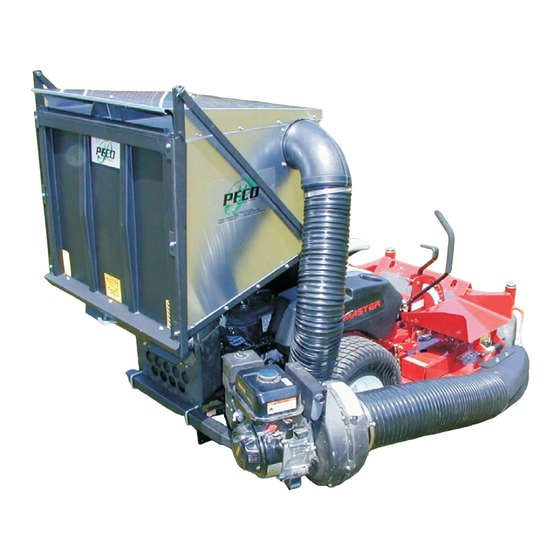
- Page 1 PECO PECO PECO PECO PECO MODEL 22621223 - 24 OPERATOR’S MANUAL ASSEMBLY MANUAL PART#: Q0309 GRASS COLLECTION DESIGNED FOR: toro z100 series OPERATION $4.00 SYSTEM MAINTENANCE REV: 0...
-
Page 2: Table Of Contents
PECO GRASS COLLECTION SYSTEM SECTION Safety Safety Alert Symbols Warranty INTRODUCTION AND DESCRIPTION 1-1 Introduction 1-2 Description PREPARATION FOR USE 2-1 Modification Of Zero Turn 2-2 Attaching The Main Frame Assembly 2-3 Attaching The Lift Handle To The Aluminum Grass Container 2-4 Attaching The Aluminum Grass Container To The ZT Mower 2-5 Aluminum Grass Container Inlet Attachment... -
Page 3: Safety Alert Symbols
WARNING! NEVER operate the mower unless the discharge guard and either the deflector assembly or the vacuum collector adapter are fastened securely in place. WARNING! Do not work around the mower deck boot or the blower area until you are certain that the mower blades and the blower impeller have stopped rotating. -
Page 4: Warranty
PECO LIMITED WARRANTY FOR NEW PRODUCTS A. WHAT IS WARRANTED? Peco extends the following warranties to the original purchaser of each new Peco consumer product subject to The following limitations. 1. PRODUCT WARRANTY: Any part of any consumer product, which is defective in material or workmanship as delivered to the purchaser will be repaired or replaced, as Peco elects, without charge for parts or labor, if the defect appears within 12 months from the date of delivery of the product to the original purchaser. -
Page 5: Introduction And Description
INTRODUCTION AND DESCRIPTION 1-1 Introduction We are pleased to have you as a PeCo customer. Your collection system has been designed to give you a low maintenance, simple, and effective way to collect the grass clippings from your ZT mower. This manual is provided to give you the necessary instructions to properly mount and operate the collection system on your ZT mower. -
Page 6: Attaching The Lift Handle To The Aluminum
2-3 Attaching The Lift Handle To The Aluminum Grass Container The various parts of the handle assembly P#(A0273) must be attached to the container frame. (Figure 4) shows the orientation and location of the components. Slide the lift handle into the slot in the handle mount bracket P#(B1730) on the grass container. - Page 7 Figure 4 Lift Handle Assy. Figure 5 Aluminum Grass Container With Handle Attached Figure 6 Latch Hook Mechanism Assembled Figure 7 Aluminum Grass Container Assy. Handle Grip Handle Mount Bracket Latch Rod...
- Page 8 Figure 8 Aluminum Grass Container Exploded View Figure 9 Misc. Parts Exploded View SHORT THROTTLE CABLE KIT A0403 MAIN FRAME ASSEMBLY B1117 OUTER ENGINE MOUNT TUBE HB0175 HARDWARE A0060 J6011 5”-6” HOSE CLAMP 6” x 32” UPPER HOSE A0318 ENGINE MOUNT TUBE B1810...
-
Page 9: Engine Mount Arm Installation
2-8 Engine Mount Arm Installation Slide the engine mount arm assembly (Figure 10) into the outer engine mount tube. Secure the engine mount arm assembly using (1) detent pin P#(J0248). Figure 10 Engine Mount Arm Detent Pin 2-9 Engine/Blower/Blade Assembly Installation Place the engine/blower/blade assembly onto the engine mount arm assembly (Figure 11). -
Page 10: Attachment Of The Boot To The Zt Mower Deck
2-13 Attachment Of The Boot To The ZT Mower Deck To mount the boot plate P#(B1810) to the boot P#(E1039), use (2) 3/8” x 1” carriage bolts P#(K1182) and (2) 3/8” flange nuts P#(K1215). Be sure that, when fastening the boot and boot plate together, the head of the bolt is placed from the inside of the boot. -
Page 11: Operating Instructions
SECTION III OPERATING INSTRUCTIONS 3-1 General Safety Only qualified people familiar with this operator’s manual and the ZT operator’s manual should operate this machine. 3-2 Operation A. Perform BEFORE EACH USE maintenance list in paragraph 4-1. B. Start the engine/blower/blade assembly. B. -
Page 12: Parts And Service
SECTION V PARTS AND SERVICE 5-1 Parts And Service Information PeCo collection system owners should record the name and telephone number of their Service Center. Your Service Center will be happy to supply replacement parts, accessories, and do any service or repairs to your collection system. -
Page 14: Notes
NOTES... - Page 15 NOTES...
- Page 16 P P P PECO PECO PECO PECO PECO ARDEN, NORTH CAROLINA 28704 (800) 438-5823 OR (828) 684-1234 FAX: (828) 684-0858 EMAIL: pecoinc1@bellsouth.net WEBSITE: WWW.LAWNVAC.COM P.O. BOX 1197...