Table of Contents
Advertisement
F F
S S
2 2
F F
S S
2 2
BEFORE RETURNING THIS PRODUCT FOR ANY
BEFORE YOU CALL, HAVE THE FOLLOWING INFORMATION AVAILABLE, CATALOG NO., TYPE NO., AND DATE CODE . IN MOST
CASES, A BLACK & DECKER REPRESENTATIVE CAN RESOLVE THE PROBLEM OVER THE PHONE. IF YOU HAVE A
SUGGESTION OR COMMENT, GIVE US A CALL. YOUR FEEDBACK IS VITAL TO BLACK & DECKER.
SAVE THIS MANUAL FOR FUTURE REFERENCE.
VEA EL ESPAÑOL EN LA CONTRAPORTADA.
POUR LE FRANÇAIS, VOIR LA COUVERTURE ARRIÈRE.
INSTRUCTIVO DE OPERACIÓN, CENTROS DE SERVICIO Y
PÓLIZA DE GARANTÍA. ADVERTENCIA: LÉASE ESTE
INSTRUCTIVO ANTES DE USAR EL PRODUCTO.
Cat.No. FS210LS
Form No. 90520749 Rev. 1
1 1
0 0
L L
S S
1 1
1 1
0 0
L L
S S
1 1
INSTRUCTION MANUAL
T
HANK YOU FOR CHOOSING
.F
WWW
IRESTORMTOOLS
TO REGISTER YOUR NEW PRODUCT
REASON PLEASE CALL 1-800-544-6986
AUG. '07
0 0
" "
T T
A A
B B
0 0
" "
T T
A A
B B
F
IRESTORM
.
/P
COM
RODUCT
Copyright
©
L L
E E
S S
A A
W W
L L
E E
S S
A A
W W
! G
O TO
R
EGISTRATION
.
2007 Black & Decker
Printed in China
Advertisement
Table of Contents

Related Manuals for Black & Decker FIRESTORM FS210LS


Summary of Contents for Black & Decker FIRESTORM FS210LS
-
Page 1: Instruction Manual
HANK YOU FOR CHOOSING BEFORE RETURNING THIS PRODUCT FOR ANY REASON PLEASE CALL 1-800-544-6986 BEFORE YOU CALL, HAVE THE FOLLOWING INFORMATION AVAILABLE, CATALOG NO., TYPE NO., AND DATE CODE . IN MOST CASES, A BLACK & DECKER REPRESENTATIVE CAN RESOLVE THE PROBLEM OVER THE PHONE. IF YOU HAVE A SUGGESTION OR COMMENT, GIVE US A CALL. -
Page 2: Safety Guidelines - Definitions
SAFETY GUIDELINES - DEFINITIONS This manual contains information that is important for you to know and understand. This information relates to protect- ing YOUR SAFETY and PREVENTING EQUIPMENT PROBLEMS. To help you recognize this information, we use the symbols to the right. Please read the manual and pay attention to these sections. Indicates an imminently hazardous situation which, if not avoided, will result in death or serious injury. - Page 3 FAILURE TO FOLLOW THESE RULES MAY RESULT IN SERIOUS INJURY. 1. FOR YOUR OWN SAFETY, READ THE INSTRUCTION MANUAL BEFORE OPERATING THE MACHINE. Learning the machine’s application, limitations, and specific hazards will greatly minimize the possibility of accidents and injury. 2.
-
Page 4: Additional Safety Rules For Table Saws
15. NEVER have any part of your body in line with the path of the saw blade. 16. NEVER REACH AROUND or over the saw blade. 17. NEVER attempt to free a stalled saw blade without first turning the machine “OFF”. 18. PROPERLY SUPPORT LONG OR WIDE workpieces. -
Page 5: Power Connections
A separate electrical circuit should be used for your machine. This circuit should not be less than #12 wire and should be protected with a 20 Amp time lag fuse. If an extension cord is used, use only 3-wire extension cords which have 3- prong grounding type plugs and matching receptacle which will accept the machine’s plug. -
Page 6: Extension Cords
15 amp. motor with a floating jackshaft gear - the most powerful in its class. This saw is designed to give high quality performance with depth of cut capacity up to 3 in. (76mm) at 90° and 2.5 in. -
Page 7: Unpacking And Cleaning
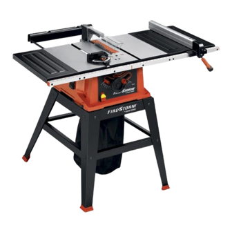
3.) 10mm wrench for splitter assembly bolts, rear supports assembly and extension wings assembly. 4.) Slotted screwdriver. 6.) Phillips screwdriver. 5.) Straight edge and/or framing square for adjustments. TABLE SAW PARTS 1- Saw 2- Left Extension Wing 3- 1/4 in.-20X1 in.Hex Head... - Page 8 RIP FENCE PARTS (11,12) 11-Rip Fence 12-Locking Handle for Rip Fence BLADE RAISING HANDWHEEL PARTS (13,14,15,16,17) 13-Blade Raising and Lowering Handwheel 14-Handle for Blade Raising and Lowering handwheel 15-Screw for Mounting Handwheel Handle 16-Cap for Handle 17-M6X1X12mm Flat Head Screw for Mounting Blade Raising and Lowering Handwheel 18-Miter Gage MITER GAGE HOLDER PARTS (19,20,21,22,23,24,25)
- Page 9 STAND PARTS 53-Leg(4) 54-Top side Bracket(2) 55-Top Front Bracket 56-Top Rear Bracket 57-Bottom side Brackets(2) 58-Bottom Front Brackets(2) 59-Foot(4) FOR YOUR OWN SAFETY, DO NOT CONNECT THE MACHINE TO THE POWER SOURCE UNTIL THE MACHINE IS COMPLETELY ASSEMBLED. DO NOT OPERATE THIS MACHINE UNTIL YOU READ AND UNDERSTAND THE ENTIRE INSTRUCTION MANUAL Fig.
- Page 10 Fig. 4, secured to the miter gage holder. 2. Assemble the miter gage holder (A) Fig. 6, to the left side of the saw cabinet using the four M4.2x10mm pan head screws (B) Fig. 7, and 3/16 in. washers (C) from inside saw cabinet.
-
Page 11: Stand Assembly
3. Then, turn saw table face up, as shown in Fig. 9C (Saw is shown fully assembled here). 4. Push down on top of the saw so the legs of the stand adjust to the surface of the floor and tighten all stand hardware and hardware which secures saw to stand. - Page 12 ASSEMBLING BLADE RAISING AND LOWERING HANDWHEEL 1. Insert special screw (C) through handle (B) Fig.10 and assembly handle to handwheel (A) by threading screw clockwise into handwheel. Then push on handle cover (D). 2. Fig. 11, illustrates the handle (B) assembled to handwheel (A).
-
Page 13: Blade Guard/Splitter Assembly
1. IMPORTANT: THE BLADE GUARD AND SPLITTER ASSEMBLY MUST BE PROPERLY ALIGNED TO THE SAW BLADE IN ORDER TO PREVENT KICKBACK. 2. Position the blade 90 degrees to the table and lock in place. Refer to page 18 “Blade Raising and Lowering Control”... - Page 14 20, are inside the slot of splitter assembly (H). 9. Using a straight edge, check to see if the splitter (H) Fig. 21, is aligned with the saw blade (R). If an adjustment is necessary, the splitter (H) can be moved left or right and rotated.
-
Page 15: Extension Wings
1/4 in. flat washers (3) 1/4 in. lockwashers (3). 3. With a straight edge, make certain the top, front and rear edges of the extension wings are level with the saw table before tightening three screws which secure extension wing to table. -
Page 16: Rip Fence
4. The rip fence is usually operated on the right hand side of the saw table. Lift lock handle (B), and position fence on table. Push downward on handle (B), to lock fence in place on saw table. - Page 17 OUTFEED SUPPORT 1. LOOSELY fasten both brackets (A) Fig. 29, to the bottom left side of the saw table as shown, using two M6x1x15mm phillips hex head screws (B) and M6.1 lockwashers (C). Assemble two remaining brackets to the bottom right side of saw table in the same manner.
-
Page 18: Starting And Stopping Saw
The on/off switch (A) Fig. 34 is located on the front of the saw cabinet. To turn the saw “ON”, move the switch (A) up to the “ON” position. To turn the saw “OFF”, move the switch (A) down to the “OFF” position. -
Page 19: Blade Tilting Control
OPERATIONS. ADJUSTING 90 AND 45 DEGREE POSITIVE STOPS Your saw is equipped with positive stops for rapid and accurate positioning of the saw blade at 90 and 45 degrees to the table. To adjust the positive stops, proceed as follows: DISCONNECT MACHINE FROM POWER SOURCE. -
Page 20: Miter Gage/Rip Fence Operation/Adjustments
ALIGNED TO THE MITER GAGE SLOT IN ORDER TO HELP PREVENT KICKBACK WHEN RIPPING. 4. The saw blade is set parallel to the miter gage slot at the factory and the fence must be parallel to the miter gage slot in order to do accurate work and prevent kickback when ripping. -
Page 21: Blade Parallel To Miter Gage Slots
2. Raise the blade to its highest position and adjust the blade so it is 90 degrees to the table. 3. Select a tooth on the saw blade that is set to the left. Mark this tooth with a pencil or marker. -
Page 22: Cross-Cutting
Start the cut slowly and hold the work firmly against the miter gage and the table. One of the rules in running a saw is that you never hang onto or touch a free piece of work. Hold the supported piece, not the free piece that is cut off. - Page 23 1. Start the motor and advance the work holding it down and against the fence. Never stand in the line of the saw cut when ripping. Hold the work with both hands and push it along the fence and into the saw blade (Fig.
- Page 24 Fig. 54. The saw and cutter overlap is shown in Fig. 55, (A) being the outside saw, (B) an inside cutter, and (C) a paper washer or washers, used as needed to control the exact width of groove.
- Page 25 2. Attach the dado head set (D) Fig. 56, to the saw arbor. NOTE: THE OUTSIDE ARBOR FLANGE CAN NOT BE USED WITH THE DADO HEAD SET, TIGHTEN THE ARBOR NUT AGAINST THE DADO HEAD SET BODY. DO NOT LOSE THE OUTSIDE ARBOR FLANGE. IT WILL BE NEEDED WHEN REATTACHING A BLADE TO THE ARBOR.
-
Page 26: Constructing A Featherboard
CONSTRUCTING A FEATHERBOARD Fig. 58, illustrates dimensions for making a typical featherboard. The material which the featherboard is constructed of, should be a straight piece of wood that is free of knots and cracks. Featherboards are used to keep the work in contact with the fence and table and help prevent kickbacks. -
Page 27: Troubleshooting Guide
TROUBLESHOOTING GUIDE BE SURE TO FOLLOW SAFETY RULES AND INSTRUCTIONS TROUBLE! SAW WILL NOT START WHAT’S WRONG? 1.Saw not plugged in. 2.Fuse blown or circuit breaker tripped. 2.Replace fuse or reset 3.Cord damaged. 4.Brushes worn out. TROUBLE! SAW MAKES UNSATISFACTORY CUTS WHAT’S WRONG? -
Page 28: Constructing A Push Stick
CONSTRUCTING A PUSH STICK When ripping work less than 4 inches wide, a push stick should be used to complete the feed and could easily be made from scrap material by following the pattern shown in Fig. 60. Fig. 60... -
Page 29: Maintenance
Recommended accessories for use with your tool are available from your local dealer or authorized service center. If you need assistance regarding accessories, please call:1-800-544-6986. The use of any accessory not recommended for use with this tool could be hazardous.. Maintenance Use only mild soap and damp cloth to clean the tool. - Page 30 À À À À MERCI D’A MERCI D’A .FIREST .FIREST POUR ENREGISTRER VOTRE NOUVEAU PRODUIT POUR ENREGISTRER VOTRE NOUVEAU PRODUIT AVANT DE RETOURNER CE PRODUIT POUR QUELQUE RAISON QUE CE SOIT, CONSERVER CE MODE D’EMPLOI POUR UN USAGE ULTÉRIEUR. MODE D’EMPLOI VOIR CHOISI FIREST VOIR CHOISI FIREST ORMT...
-
Page 31: Règles Générales De Sécurité
LIGNES DIRECTRICES EN MATIÈRE DE SÉCURITÉ — Ce mode d’emploi contient de l’information qu’il est important de connaître et de comprendre. Cette information concerne VOTRE SÉCURITÉ et vise à ÉVITER TOUT PROBLÈME D’ÉQUIPEMENT. Pour vous aider à reconnaître ces informations, nous utilisons les symboles à droite. Veuille lire le mode d’emploi et porter une attention accrue à ces sections. - Page 32 RÈGLES GÉNÉRALES DE SÉCURITÉ AVERTISSEMENT NÉGLIGER DE SUIVRE CES RÈGLES RISQUE D’ENTRAÎNER DES BLESSURES GRAVES. POUR SA PROPRE SÉCURITÉ, LIRE LE MODE D’EMPLOI AVANT D’UTILISER L’OUTIL. L’apprentissage de l’utilisation de cet outil, des restrictions, et des risques qui lui sont propres réduit grandement la possibilité d'accidents et de blessures.
- Page 33 RÈGLES DE SÉCURITÉ SUPPLÉMENTAIRES POUR AVERTISSEMENT LIRE ATTENTIVEMENT TOUTES LES MISES EN GARDE ET DIRECTIVES D’UTILISATION AVANT D’UTILISER CET ÉQUIPEMENT. À défaut de suivre les directives sous-mentionnées, un choc électrique, un incendie, des dommages ou une blessure corporelle grave pourraient survenir. 1.
-
Page 34: Connexions Électriques
CONNEXIONS ÉLECTRIQUES Un circuit électrique séparé doit être utilisé pour l’appareil. Ce circuit doit utiliser un câble de calibre 12 au minimum et doit être protégé par un fusible temporisé de 20 A. Si vous utilisez une rallonge, n’utiliser que des rallonges à 3 fils pourvues d’une fiche de mise à... -
Page 35: Avant-Propos
Utiliser les rallonges appropriées S’assurer que la rallonge est en bon état et qu’il s’agit d’une rallonge à ATTENTION 3 fils avec une fiche de mise à la terre à 3 broches et prise de courant compatible avec la fiche de l’appareil. Lorsque qu’une rallonge est utilisée, s’assurer d’en utiliser une de calibre suffisamment élevé... - Page 36 DÉSEMBALLAGE ET NETTOYAGE Désemballer soigneusement la machine et toutes les pièces de ou des emballages d’expédition. Retirer le revêtement protecteur de toutes les surfaces non peintes. Le revêtement peut être retiré avec un chiffon doux humidifié avec du kérosène (ne pas utiliser d’acétone, d’essence ou de diluant à laque). Après le nettoyage, couvrir les surfaces non peintes d’une cire à...
- Page 37 Fig. 2 PIÈCE DU GUIDE LONGITUDINAL (11,12) 11– Guide longitudinal 12– Poignée de verrouillage du guide longitudinal PIÈCES DU VOLANT DE RELÈVEMENT DE LA LAME (13,14,15,16,17) 13– Volant d’abaissement et de relèvement de la lame 14– Poignée du volant d’abaissement et de relèvement de la lame 15–...
- Page 38 PIÈCES DU SOCLE 53– (4) pattes 54– (2) traverses supérieures latérales 55– Traverse supérieure avant 56– Traverse supérieure arrière 57– (2) traverses inférieures latérales 58– (2) traverses inférieures avant 59– (4) pieds POUR VOTRE PROPRE SÉCURITÉ, NE PAS BRANCHER L’APPAREIL À UNE SOURCE AVERTISSEMENT D’ALIMENTATION JUSQU’À...
-
Page 39: Assemblage Du Socle
PORTE-GUIDE D’ONGLET DÉBRANCHER L’APPAREIL DE LA SOURCE D’ALIMENTATION. AVERTISSEMENT 1. Assembler l’attache à ressort (E) fig. 4, au porte-guide d’onglet (A) comme indiqué avec une vis cylindrique à dépouille (F) M4x0,7x10 mm, un contre-écrou 4,8 mm (3/16 po) et un écrou hexagonal M4x0,7. NOTE : l’écrou hexagonale (G) fig. - Page 40 2. La fig. 11 illustre la poignée (B) assemblée sur le volant (A). 3. Assembler le volant (A) fig. 12, sur l’arbre (B) tout en s’assurant que le méplat de l’intérieur du volant s’aligne avec le méplat de l’arbre. 4. Fixer le volant (A) fig. 13, à l’arbre (B) fig. 12, avec une vis à tête plate M6x1x12 mm (C) fig. 13. ENSEMBLE DE PROTÈGE-LAME ET COUTEAU SÉPARATEUR DÉBRANCHER L’APPAREIL DE LA SOURCE D’ALIMENTATION.
- Page 41 ASSEMBLAGE DE LA BARRE DE GUIDAGE À LA SCIE DE TABLE 1.Tenir la barre de guidage avec les grands trous face à vous. Serrer lâchement les barres de guidage (A) fig. 24, au quatre trous filetés (B) de la table de la scie (C) avec deux longues vis (D) de 6,4 m - 20 x 31,2 mm (1/4 po - 20 x 1 1/4 po) (D), des contre-écrous (E) et des cales (F).
- Page 42 S’ASSURER QUE L’INTERRUPTEUR SE TROUVE SUR LA POSITION D’ARRÊT AVANT DE AVERTISSEMENT BRANCHER LE CORDON D’ALIMENTATION. EN CAS DE PANNE DE COURANT, METTRE L’INTERRUPTEUR SUR LA POSITION D’ARRÊT. UN DÉMARRAGE ACCIDENTEL PEUT PROVOQUER DES BLESSURES. VERROUILLER L’INTERRUPTEUR EN POSITION D’ARRÊT IMPORTANT : lorsque l’outil est inutilisé, l’interrupteur doit être verrouillé...
- Page 43 RÉGLAGE D’UNE BUTÉE FIXE À 45 DEGRÉS 4. Desserrer la poignée de blocage de l’inclinaison de la lame, déplacer le mécanisme d’inclinaison de la lame le plus à droite possible, et serrer la poignée de blocage de l’inclinaison de la lame. 5.
-
Page 44: Changement De La Lame
1. DÉBRANCHER L’APPAREIL DE LA SOURCE D’ALIMENTATION. 2. Relever la lame au maximum et la régler de sorte qu’elle se trouve à 90° par rapport à la table. 3. Sélectionner une dent de la lame qui se trouve sur la gauche. Marquer cette dent à l’aide d’un crayon ou d’un marqueur. - Page 45 Pour une sécurité accrue et plus de commodité, ajouter au guide d’onglet un parement auxiliaire en bois Fixer le parement en bois à l’avant du guide d’onglet en insérant deux vis à bois dans les trous (A) fig. 46, à cet effet sur le corps du guide d’onglet et dans le parement en bois.
- Page 46 1. Le rainurage consiste à couper une feuillure ou une rainure large dans la pièce. La plupart des ensembles à rainurer sont constitués de deux lames externes et de quatre ou cinq couteaux internes (fig. 53). De nombreuses combinaisons de lames et couteaux sont utilisées pour couper des rainures de 3,2 mm (1/8 po) à 20,6 mm (13/16 po) pour des étagères, pour réaliser des assemblages, tenonnage, rainurage, etc.
-
Page 47: Guide De Dépannage
SUIVRE LES RÈGLES ET CONSIGNES DE SÉCURITÉ PROBLÈME ! LA SCIE NE DÉMARRE PAS QUEL EST LE PROBLÈME ? 1.Scie non branchée. 2.Fusible grillé ou disjoncteur déclenché.2.Remplacer le fusible ou réinitialiser le disjoncteur. 3.Cordon endommagé. 4.Brosses usées. PROBLÈME ! LES DÉCOUPES EFFECTUÉES PAR LA SCIE NE SONT PAS SATISFAISANTES QUEL EST LE PROBLÈME ? 1.Lame émoussée. - Page 48 FABRICATION D'UN POUSSOIR » « Pour scier en long un ouvrage de moins de 10,2 cm (4 po) de large, utiliser un poussoir pour terminer la coupe. Il est facile de fabriquer un poussoir avec des déchets de découpe en suivant le modèle indiqué à la fig. 60.
-
Page 49: Entretien
Les accessoires recommandés pouvant être utilisés avec l’outil sont disponibles auprès de votre distributeur local ou centre de réparation autorisé. Pour tout renseignement concernant les accessoires, composer le : 1-800-544-6986 AVERTISSEMENT l’utilisation de tout accessoire non recommandé avec l’outil pourrait s’avérer dangereuse. Entretien N’utiliser qu’un détergent doux et un chiffon humide pour nettoyer l’outil. - Page 50 ” ” ” ” MANUAL DE INSTRUCCIONES ¡GRACIAS POR ELEGIR FIRESTORM! VAYA A WWW.FIRESTORMTOOLS.COM/ PRODUCTREGISTRATION PARA REGISTRAR SU NUEVO PRODUCTO. ANTES DE DEVOL VER ESTE PRODUCTO POR CUALQUIER MOTIVO, LLAME AL ANTES DE DEVOL VER ESTE PRODUCTO POR CUALQUIER MOTIVO, LLAME AL (55) 5326-7100 (55) 5326-7100 CONSERVE ESTE MANUAL PARA FUTURAS CONSULTAS...
-
Page 51: Normas Generales De Seguridad
DEFINICIONES DE LAS NORMAS DE SEGURIDAD Es importante que usted conozca y comprenda la información incluida en este manual. Esta información se relaciona con la protección de SU SEGURIDAD y la PREVENCIÓN DE PROBLEMAS CON EL EQUIPO. Para ayudarlo a reconocer esta información, utilizamos los símbolos que se incluyen a la derecha. - Page 52 NORMAS GENERALES DE SEGURIDAD LA FALTA DE CUMPLIMIENTO DE ESTAS NORMAS PUEDE PROVOCAR LESIONES GRAVES. INSTRUCCIONES IMPORTANTES SOBRE SEGURIDAD PARA SU PROPIA SEGURIDAD, LEA EL MANUAL DE INSTRUCCIONES ANTES DE UTILIZAR LA MÁQUINA. Al aprender la aplicación, las limitaciones y los peligros específicos de la máquina, se minimizará...
- Page 53 NORMAS DE SEGURIDAD ADICIONALES PARA LAS LEA Y COMPRENDA TODAS LAS ADVERTENCIAS Y LAS INSTRUCCIONES DE OPERACIÓN ANTES DE UTILIZAR ESTE EQUIPO. EL INCUMPLIMIENTO DE CUALQUIERA DE LAS INSTRUCCIONES ENUMERADAS A CONTINUACIÓN PUEDE PROVOCAR DESCARGA ELÉCTRICA, INCENDIO O LESIONES PERSONALES GRAVES O DAÑOS A LA PROPIEDAD. UTILICE ESTA MÁQUINA...
-
Page 54: Conexiones Eléctricas
Debe utilizar un circuito eléctrico independiente para su máquina. Este circuito no debe ser menor a un cable Nº 12 y debe estar protegido con un fusible de acción retardada de 20 amperios. Si utiliza un cable prolongador, debe ser únicamente de 3 conductores, que tenga enchufe a tierra de 3 patas y tomacorrientes correspondientes que acepten el enchufe de la máquina. -
Page 55: Cables Prolongadores
CABLES PROLONGADORES Use los cables prolongadores apropiados. Asegúrese de utilizar un cable prolongador en buenas condiciones y de que sea uno de 3 conductores con enchufe a tierra de 3 patas y el tomacorriente correspondiente que se adapte al enchufe de la máquina. Cuando utilice un cable prolongador, compruebe que tenga la capacidad para conducir la corriente de la máquina. -
Page 56: Desembalaje Y Limpieza
DESEMBALAJE Y LIMPIEZA Desembale cuidadosamente la máquina y todos los elementos sueltos del o los contenedores de envío. Quite el recubrimiento protector de todas las superficies sin pintura. Puede quitarlo con un trapo suave humedecido con queroseno (no utilice acetona, gasolina ni solvente de barniz para este fin). Luego de limpiar, cubra las superficies sin pintura con cera en pasta de buena calidad que se utiliza para los pisos del hogar. - Page 57 Fig. 2 PARTES DE LA GUÍA DE CORTE LONGITUDINAL (11,12) 11- Guía de corte longitudinal 12- Mango de bloqueo para la guía de corte longitudinal PARTES DEL VOLANTE PARA ELEVAR LA HOJA (13,14,15,16,17) 13- Volante para elevar y bajar la hoja 14- Mango del volante para elevar y bajar la hoja 15- Tornillo para montar el mango del volante 16- Tapa para el mango...
- Page 58 PARTES DE LA BASE 53- Pata (4) 54- Abrazadera lateral superior (2) 55- Abrazadera frontal superior 56- Abrazadera trasera superior 57- Abrazaderas superiores laterales (2) 58- Abrazaderas frontales inferiores (2) 59- Pie (4) POR SU PROPIA SEGURIDAD, NO CONECTE LA MÁQUINA A LA FUENTE DE ALIMENTACIÓN HASTA QUE ESTÉ...
- Page 59 ENSAMBLAJE DE LA BASE 1. Las patas de la base poseen protuberancias que deben alinearse con los orificios en las abrazaderas superiores e inferiores. Ensamble la base como se muestra en la Fig. 9A, con 16 pernos de soporte y tuercas de bloqueo hexagonales.
- Page 60 3. Ajuste la abrazadera para el soporte del hendedor (A), Fig. 14, a la abrazadera del hendedor (B) con dos tornillos de cabeza hexagonal 1/4-20 x 1/2" (C) y dos arandelas de bloqueo de diente externo de 6,35 mm (1/4") como se muestra.
- Page 61 GUÍA DE CORTE LONGITUDINAL 1. Visser l’écrou hexagonal M8x de 1,25 (A) fig. 26 à mi-chemin sur le goujon de la poignée (B). 2. Fixer la poignée (B) fig. 26 dans le trou fileté (C) de la came du guide. Serrer l'écrou hexagonal (A) fig. 26 contre la came (D).
- Page 62 CONTROL DE ELEVACIÓN Y DESCENSO DE LA HOJA Para elevar o bajar la hoja de la sierra, gire el volante (A), Fig. 36. Si gira el volante en el sentido de las agujas del reloj, la hoja descenderá y si lo gira en el sentido contrario a las agujas del reloj, la hoja se elevará. EL MANGO DE BLOQUEO DE INCLINACIÓN DE LA HOJA (B), FIG.
-
Page 63: Cambio De La Hoja
4. La hoja de la sierra viene instalada de fábrica en forma paralela a la ranura del calibrador de inglete y la guía debe estar en paralelo a la ranura del calibrador de inglete para poder realizar un trabajo exacto y evitar el retroceso al cortar longitudinalmente. -
Page 64: Corte Transversal
OPERACIONES MÁS COMUNES DE CORTE CON SIERRA Las operaciones comunes de corte con sierra incluyen los cortes longitudinales y transversales, además de algunas otras operaciones estándar fundamentales. Como sucede con todas las máquinas eléctricas, hay un determinado margen de peligro relacionado con el funcionamiento y el uso de la máquina. El uso de la máquina de conformidad con las medidas de seguridad, y con la precaución que éstas exigen, disminuirá... - Page 65 NOTA: algunas operaciones especiales requieren que se incorpore a la guía un revestimiento de madera auxiliar, como se explica en la sección “UTILIZACIÓN DE UN REVESTIMIENTO DE MADERA EN LA GUÍA DE CORTE LONGITUDINAL”, y el uso de una vara para empujar. UTILIZACIÓN DE UN REVESTIMIENTO DE MADERA EN LA GUÍA DE CORTE LONGITUDINAL Los revestimientos de madera (A) Fig.
- Page 66 CONSTRUCCIÓN DE UNA TABLA DE CANTO BISELADO La Fig. 58 ilustra las dimensiones para realizar una tabla de canto biselado típica. El material de la tabla de canto biselado debe ser una pieza de madera recta que no tenga nudos ni grietas. Las tablas de canto biselado se utilizan para mantener el trabajo en contacto con la guía y la mesa y para prevenir retrocesos.
- Page 67 CONSTRUCCIÓN DE UNA VARA PARA EMPUJAR Cuando realice un corte longitudinal en una pieza con un ancho menor a 10 cm (4 pulgadas), puede utilizar una vara para empujar a fin de completar la introducción en la hoja. Esta vara se puede hacer fácilmente con material de desecho, siguiendo la ilustración de la Fig.
-
Page 68: Especificaciones
Los accesorios que se recomiendan para la herramienta están disponibles en su distribuidor local o en el centro de mantenimiento autorizado. Si necesita ayuda con respecto a los accesorios, llame al: (55)5326-7100. el uso de accesorios no recomendados para utilizar con esta herramienta puede resultar peligroso. Mantenimiento Para limpiar la herramienta, sólo utilice jabón suave y un paño húmedo.