Table of Contents
Advertisement
RETAIN THESE INSTRUCTIONS
FOR FUTURE REFERENCE
INSTALLATION
INSTRUCTIONS
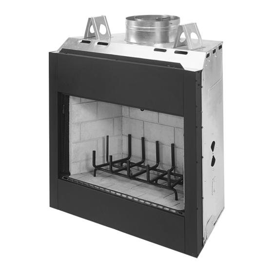
CUSTOM SERIES
36" Wood Burning Fireplaces
P/N 700,009M REV. D 11/2003
MODELS
RD-36
HC-36
RD-36-H
HC-36-H
RDI-36
HCI-36
RDI-36-H
HCI-36-H
This installation manual will enable you to obtain a safe, efficient and
dependable installation of your fireplace system. Please read and under-
stand these instructions before beginning your installation.
Do not alter or modify the fireplace or its components under any
circumstances. Any modification or alteration of the fireplace system,
including but not limited to the fireplace, chimney components and
accessories, may void the warranty, listings and approvals of this system
and could result in an unsafe and potentially dangerous installation.
IMPORTANT! TO ASSURE PROPER ALIGNMENT OF GLASS DOORS:
INSTALL THIS FIREPLACE IN A SQUARE AND PLUMB CONDITION,
USING SHIMS AS NECESSARY AT SIDES AND/OR BOTTOM.
PLEASE RETAIN THIS MANUAL FOR FUTURE REFERENCE.
WH Report No. J9902-5865C-231
Page 1
Advertisement
Table of Contents

Related Manuals for Superior CUSTOM SERIES RD-36


Summary of Contents for Superior CUSTOM SERIES RD-36
- Page 1 RETAIN THESE INSTRUCTIONS FOR FUTURE REFERENCE INSTALLATION INSTRUCTIONS CUSTOM SERIES 36" Wood Burning Fireplaces P/N 700,009M REV. D 11/2003 MODELS RD-36 RD-36-H RDI-36 RDI-36-H This installation manual will enable you to obtain a safe, efficient and dependable installation of your fireplace system. Please read and under- stand these instructions before beginning your installation.
-
Page 2: Table Of Contents
TABLE OF CONTENTS Safety Rules ... page 2 Tools and Building Supplies ... page 2 Precautions ... page 3 Introduction ... page 3 Clearances/Height Requirements ... page 3 Chimney System ... page 3 Assembly Outline ... page 4 Location of Fireplace ... page 4 Assembly Steps ... -
Page 3: Precautions
PRECAUTIONS Note: These fireplace systems are not difficult to install. However, in the interest of safety, it is recommended that the installer be a qualified or certified “tradesman” familiar with commonly accepted fireplace installation and safety tech- niques as well as prevailing local codes. The most important areas of concern dealing with the installation of factory-built fireplaces are clearances to combustible materials, proper... -
Page 4: Assembly Outline
Insulate Joists Same As Ceiling Draft Stops Firestop CTDT Termination Note: Non- Combustible Chase Flashing Must Be Used To Cover Chase Opening Level Solid Continuous Surface Insulation (Thermal Barrier) Figure 2 WARNING: IF INSULATION IS USED, THE FIREPLACE MUST NOT BE PLACED DI- RECTLY AGAINST IT. -
Page 5: Assembly Steps
ASSEMBLY STEPS Note: The following steps represent the normal sequence of installation. Each installation is unique, however, and might require a different sequence. 1. Position firebox prior to framing or into prepared framing. 2. Install the chimney system. 3. Connect house wiring to the fireplace for later attachment of optional blower. -
Page 6: Fireplace Specifications
" Metal Safety Strips Figure 8 Metal Safety Strips Figure 9 Step 3. Refer to fireplace drawings and specifi- cations on pages 6 and 7 for framing dimensions and details. Frame appliance enclosure as illus- trated in Figures 11 through 14 on page 8. IMPORTANT: UNDER NO CIRCUMSTANCES CAN THE FIREPLACE TOP SPACERS ( FIGURE 10 ) BE REMOVED OR MODIFIED, NOR MAY... -
Page 7: Framing Specifications
FRAMING SPECIFICATIONS Header Fireplace Framing Note: When Framing With 6” Studs Header Must Be 17” (432mm) Higher. Use Security’s OR15 Offset/Return Elbow To Recess The Chimney Back 2 1/2” (64mm). Maintain Required Clearance To Chimney At All Times. Figure 11 Back Wall of Chase/Enclosure FOAK Combustion Including Finising Materials if any... -
Page 8: Installing The Chimney System
Step 4. Fireplace should be secured to side framing members using the full length nailing tabs at the top and bottom of the fireplace front face. Use 8d nails ( Figure 17 ). 8d Nail Figure 17 Note: The nailing tabs and the area directly behind the nailing tabs are exempt from the clearances described on page 5. -
Page 9: Offset Through Floor/Ceiling
Note: If there is a room above ceiling level, firestop spacer must be installed on the bottom side of the ceiling. If an attic is above ceiling level, firestop spacer must be installed on top side of ceiling joist (Figures 21 and 22 ). Room Above Firestop Spacer Figure 21... - Page 10 Security chimney sections do not need to be screwed together. Additional reinforcement is not necessary except in certain offset condi- tions (refer to page 14, Figure 39 ). Step 5. The height of vertical chimney pipe supported only by the fireplace must not ex- ceed 30'.
-
Page 11: Ten Foot Rule Summary
Using a FTF8-CTDT Chase Termination: Refer to specific installation instructions in- cluded with the FTF8-CTDT chase termination for clearance and installation details. Using a FTF8-CT1 Chase Termination: Refer to specific installation instructions in- cluded with FTF8-CT1 chase terminations for clearance and installation details. Using a FTF8-CT2 Chase Termination: Refer to specific installation instructions in- cluded with FTF8-CT2 chase terminations for... -
Page 12: Special Offset Instructions
4. Determine amount of chimney height re- quired by subtracting total combined height of all pre-selected components (fireplace and chimney components from total desired height.) Reference Vertical Elevation Chart and deter- mine the number of chimney sections (quantity and length) required. SPECIAL OFFSET INSTRUCTIONS To clear any overhead obstructions, you may offset your chimney system using Security's... -
Page 13: Offset Elevation Chart
Return Elbow Max. Stabilizer 10' Max. Offset Elbow Figure 37 Figure 38 OFFSET ELEVATION CHART FTF8-ES30 Offset Height Offset/Return FTF8-S4 (Inches) (Inches) Elbow Stabilizer NOTE: DIAGRAMS & ILLUSTRATIONS NOT TO SCALE. Number of FTF8 Chimney Sections 12" 18" 38" 48"... -
Page 14: Installing Offsets
Joints Chimney Section No. 8 x 1/2" SMS Figure 39 Underside Of Chimney Figure 40 FTF8-E30 Return Elbow* Chimney Section (S) FTF8-30 Offset Elbow* *Part of Offset/Return Package Model FTF8-ES30 Figure 41 INSTALLING OFFSETS First, review the Offset Elevation Chart and Figure 41 for reference. -
Page 15: Combustion Air Kits
BLOWER THREE PRONGED PLUG TO GROUNDED OUTLET Figure 44 The FBK-100/200 Blower Kits are design cer- tified by Warnock Hersey for use with these appliances. Always check local building codes. Installation of the FBK Blower Kits must comply with local regulations as well as the National Electric Code. -
Page 16: Glass Doors
Glass Doors If glass doors are to be installed on these fireplaces, refer to specific installation instruc- tions packed with the glass doors. Use only the doors that are listed for use with these fire- places. Use of other non-listed glass door on these fireplaces may constitute a potential fire hazard and is not recommended. - Page 17 A wall shield is required where a continuous perpendicular side wall is within 12" of the fireplace opening, ( Figure 49 ). Use a 24" W x 30" H wall shield constructed of millboard or a durable, noncombustible material having an equal or greater insulating value than K = .54BTU/ IN FT HR F.
-
Page 18: Finish Requirements
" marble slab set in " mortar covers the brick, “R” for the marble and mortar becomes: “R” = r x T = 0.09 x " = .068 “R” = r x T = 0.20 x " = .10 The sum of all “R values” is: .70 + .10 +. -
Page 19: Installation Components
INSTALLATION COMPONENTS Firestop Spacer (30 ) 63L32 F8FS30-2 Offset/ Return Package (30 ) 63L22 FTF8-ES30 Stabilizer 63L25 FTF8-S4 Storm Collar 63L59 Locking Band 63L60 Firestop Spacer (Flat) 63L31 F8FS-2 (FBK-200 Models Only) Forced Air Blower Kits -Single Speed 80L84 -Variable Speed 80L85 63L38 Flashing... - Page 20 The manufacturer reserves the right to make changes at any time, without notice, in design, materials, specifications, prices and also to discontinue colors, styles and products. Consult your local distributor for fireplace code information. Printed in U.S.A. © 2000 by LENNOX P/N 700,009M REV.