Advertisement
Quick Links
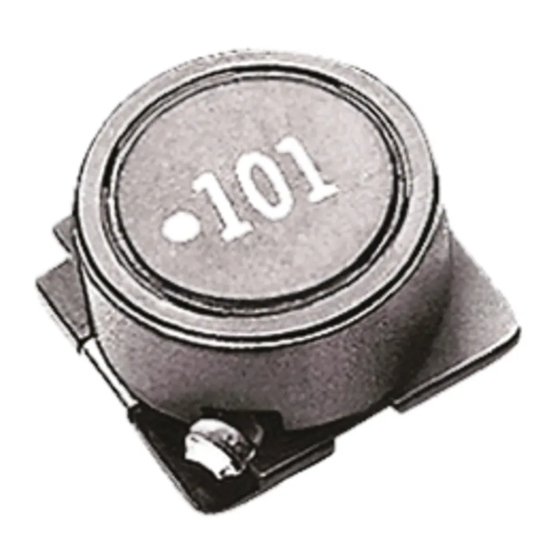
SMD Inductors(Coils)
For Power Line(Wound, Magnetic Shielded)
SLF Series SLF12565
FEATURES
• The SLF series are characterized by low profile, low DC
resistance, and high current handling capacities.
• Because they are magnetically shielded, these parts can be
used in high-density mounting configurations.
• Flat bottom surface ensures secure, reliable mounting.
• Provided in embossed carrier tape packaging for use with
automatic mounting machines.
APPLICATIONS
Portable telephones, personal computers, hard disk drives, and
other electronic equipment.
SPECIFICATIONS
Operating temperature range
Storage temperature range
RECOMMENDED REFLOW SOLDERING CONDITIONS
250±5˚C
230˚C
180˚C
150˚C
120s
Preheating
Time ( s )
• Conformity to RoHS Directive: This means that, in conformity with EU Directive 2002/95/EC, lead, cadmium, mercury, hexavalent chromium, and specific
bromine-based flame retardants, PBB and PBDE, have not been used, except for exempted applications.
• All specifications are subject to change without notice.
–20 to +105°C
[Including self-temperature rise]
–40 to +105°C[Unit of products]
5s
Natural
cooling
30s
PRODUCT IDENTIFICATION
SLF 12565 T- 220 M 3R5 - PF
(1)
(2)
(3) (4) (5) (6)
(1) Series name
(2) Dimensions
12565
12.5× 12.5× 6.5mm (L× W× T)
(3) Packaging style
T
Taping(reel)
(4) Inductance value
2R0
2µH
100
10µH
(5) Inductance tolerance
M
±20%
N
±30%
(6) Rated current
1R6
1.6A
3R5
3.5A
(7) Lead-free compatible product
PF
Lead-free compatible product
PACKAGING STYLE AND QUANTITIES
Packaging style
Taping
Conformity to RoHS Directive
(7)
Quantity
500 pieces/reel
002-05 / 20060928 / e531_slf12565.fm
(1/2)
Advertisement

Related Manuals for TDK SLF Series SLF12565


Summary of Contents for TDK SLF Series SLF12565
- Page 1 SMD Inductors(Coils) For Power Line(Wound, Magnetic Shielded) SLF Series SLF12565 FEATURES • The SLF series are characterized by low profile, low DC resistance, and high current handling capacities. • Because they are magnetically shielded, these parts can be used in high-density mounting configurations.
- Page 2 SHAPES AND DIMENSIONS/RECOMMENDED PC BOARD PATTERN Marking ( Inductance code ) 12.5±0.3 6.5±0.35 Winding start mark 0.1typ. Weight: 3.2g Dimensions in mm ELECTRICAL CHARACTERISTICS Inductance Inductance Test frequency (µH) tolerance L (kHz) ±30% ±30% ±30% ±20% ±20% ±20% ±20% ±20% ±20% ±20% ±20%...