
Related Manuals for Sony DFS-700


Summary of Contents for Sony DFS-700
- Page 1 3-203-834-12(1) DME Switcher Operating Instructions Before operating the unit, please read this manual thoroughly and retain it for future reference. DFS-700/700P 2000 Sony Corporation...
- Page 2 Owner’s Record The model and serial numbers are located in the rear. Record these numbers in the spaces provided below. Refer to them whenever you call upon your Sony dealer regarding this product. Model No. Serial No. WARNING To prevent fire or shock hazard, do not expose the unit to rain or moisture.
-
Page 3: Table Of Contents
Table of Contents Chapter 1 Overview Chapter 2 Location and Function of Parts and Controls Chapter 3 Basic Operation Features of This System ...1-1 Option Boards ...1-3 Control Panel ... 2-1 Processor Unit ...2-13 Front Panel ... 2-13 Rear Panel ... 2-13 DME Switcher Introduction ... - Page 4 Table of Contents Chapter 3 Basic Operation (Continued) Chapter 4 Advanced Operations Table of Contents Inserting Characters and Graphics (1) — Title Key ...3-33 Luminance Key ... 3-33 Chroma Keying ... 3-36 Masking Part of a Title Key... 3-44 Inserting Characters and Graphics (2) — Downstream Key ...
- Page 5 Chapter 5 Control From Editing Control Units Chapter 6 System Connections and Settings Control From the PVE-500 ... 5-1 Preparations ... 5-2 Cut Editing ... 5-2 A/B Roll Editing ... 5-3 Control From the BVE-600... 5-5 Preparations ... 5-5 A/B Roll Editing ... 5-6 Control From the BVE-900/2000 Series ...5-8 Preparations ...
- Page 6 Table of Contents Appendixes Table of Contents Warning Messages ... A-1 Effect Type List ... A-3 Effect Control Parameter List ... A-5 Effect Motion Types ... A-21 Effect Pattern Variant Forms and Decorations ... A-22 Effect Pattern Image List ... A-29 To Exchange the Button Labels ...
-
Page 7: Features Of This System
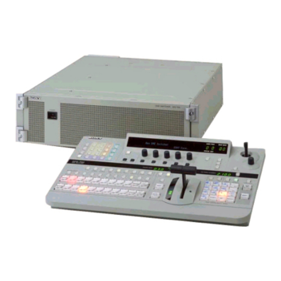
Features of This System The Sony DFS-700/700P DME Switcher is a Digital Multi Effects system, offering high-performance effects at high image quality. The system consists of a processor unit and control panel. Support for fully digital component systems with SDI inputs and outputs This system provides SDI interfaces as standard equipment. - Page 8 Features of This System Color correction function A YUV color correction function is provided for white balance adjustment and general color adjustment. User program effect and snapshot function • User program effects: This system has a large number of built-in effects, but also allows the user to create original effects, and save them in memory, for execution in the same way as the built-in effects.
-
Page 9: Option Boards
Option Boards The DFS-700/700P system has the following option boards. BKDF-701 SDI and Component Input Board When this board is installed, it allows all eight video inputs to be used as either SDI or analog component inputs. When using this board, you can select the types of the optional inputs individually, using the setup menu. -
Page 11: Control Panel
Control Panel This section describes the control panel, which is divided into several sections, as shown below. See the page numbers shown in parenthesis for more details. 6 EDITOR and GPI buttons (see page 2-7) 7 Menu control section (see page 2-7) 8 Effect control section TITLE EDGE... - Page 12 Control Panel 1 Delegation section 1 Delegation buttons AUXILIARY 2 AUXILIARY buttons BLACK 1 Delegation buttons Use these buttons to delegate the input signal corresponding to the selected AUXILIARY button to the corresponding function. Pressing one of these buttons lights it, and the corresponding AUXILIARY button also lights.
- Page 13 2 Primary cross-point bus section BACKGROUND 1 BACKGROUND bus buttons BLACK FOREGROUND 2 FOREGROUND bus buttons BLACK 1 BACKGROUND bus buttons Select the image to form the background for an effect. Select from the following buttons. BLACK button: Select the black burst signal generated by the internal synchronizing signal generator in this unit.
- Page 14 Control Panel 3 Effect transition section 1 TRANS RATE display window TRANS RATE 4 MIX button 5 EFFECT button 6 TITLE button 7 CUT button 8 AUTO TRANS button 1 TRANS (transition) RATE display window This shows the transition time for effects, downstream keys, and fade-to-black, in units of frames.
- Page 15 9 N/R (normal/reverse) button To carry out an effect in normal/reverse (i.e. alternating) mode, press this button, turning it on. It lights automatically for animation effects and title keys. q; REV (reverse) button To carry out an effect in the reverse direction, press this button, turning it on.
- Page 16 Control Panel 5 PATTERN/KEY PAD buttons These function as shown in the following table, according to the selected mode. Button PATTERN DIRECT PATTERN 0 to 9 Select the Set the pattern pattern shown number. on the button. LAST X/INS – –...
- Page 17 3 DSK (downstream keyer) button Press this button, turning it on, to insert the downstream key set by the DSK section buttons in the menu control section into the program output video. By pressing the SET button in the effect transition section, you can set the downstream key transition time.
- Page 18 Control Panel MASK button: Press this button to mask off a part of the key source signal. When you press this button, it lights, and the system is now in mask mode, and you can select a rectangular mask in the effect control section.
- Page 19 4 CCR, LIGHTING, and MATTES buttons CCR (color corrector) button: Press this button to use the color corrector. When you press this button, it lights, and you can adjust the color corrector settings in the effect control section. Press the button once more to turn it off and exit the color corrector.
- Page 20 Control Panel 8 Effect control section 1 Menu display 2 INITIAL button 3 PAGE button 4 PATTERN ADJ button 1 Menu display This shows system and effect settings. Watch this display while checking and adjusting the settings. Menu name or pattern number Settings INIT SETUP--SNAP--USRPGM--KEYPAD EXEC Setting values (ON/OFF or parameter values)
- Page 21 • Changing a setting value preceded by “+” (setup menu operations) Hold down the corresponding F button (F1 to F5), and turn the control knob. • Changing a setting value followed by “+” (user program effect setting operations) Hold down the corresponding F button (F1 to F5), and enter the numeric value using the numeric keypad.
- Page 22 Control Panel 4 HOLD INPUT button To hold the primary cross-point bus settings and the auxiliary bus settings (signal selections) fixed when recalling a snapshot, press this button. When you press this button, it lights, and when you recall a snapshot, the system is in the hold input mode.
-
Page 23: Processor Unit
Processor Unit Front Panel Power indicator Power switch Power switch and indicator This powers the unit on and off. Press the “ ” side of the switch to power on, and the “ ” side to power off. When the power is on, the power indicator lights amber. -
Page 24: Processor Unit
Processor Unit 1 PGM OUT (program output) connectors These output the final program output, that is, the video to which effects have been applied. Connect to VTR (recorder) and program monitor video input connectors. The following four types of output are provided, each with two channels (1 and 2). - Page 25 7 CLEAN OUT connector (BNC-type) Outputs serial digital signals (270 MHz). Using the setup menu, you can select the output from the following three signals. CLEAN OUT: The program output signal, without the downstream key inserted. PVW OUT: The signal output is the same as the program output after completion of the effect transition.
-
Page 27: Dme Switcher Introduction
Execute the effect (see page 3-54) Basic Operation This section selects two of the many effects provided by the DFS-700/ 700P as examples, and describes the basic flow of operations to use them. It also describes the demonstration function, which automatically executes one hundred sample effects. -
Page 28: Example Operation (1): Wipe
DME Switcher Introduction Example Operation (1): Wipe Setting items Program output Start of effect Chapter 3 Basic Operation In this example we’ll use the AUTO TRANS button, to make a wipe, with the new image appearing from the center of the screen. As an example, we’ll set the control panel as follows. - Page 29 Procedure <Preparation> <Image selection> <Effect selection> TITLE EDGE EDITOR TRAIL SHADOW BORDER BEVELD EDGE INITIAL SET UP MASK MASK MASK SOFT SHIFT LIGHTING MATTES BORDER PATTERN PAGE TRANS RATE TITLE 1 TITLE 2 SUPER BG FRGD 2 MEMORY FRAME FREEZ SOURCE SOURCE FILL...
- Page 30 DME Switcher Introduction <Transition time setting> Chapter 3 Basic Operation Press button 9 in the pattern/numeric keypad. The button lights, and this selects the wipe assigned to this button (pattern number 24). The PATTERN NUMBER display window shows “0024”. Press the SET button once or twice, so that the EFFECT display window mode indicator lights.
-
Page 31: Example Operation (2): Picture-In-Picture
Example Operation (2): Picture-in-Picture Setting items Program output Using the fader lever, we’ll insert the foreground image within the background image. We’ll apply a border around the edge of the foreground image. As an example, we’ll set the control panel as follows. Background image: internal video signal (color background ) Foreground image: video signal connected to the VIDEO INPUT 1 connector... - Page 32 DME Switcher Introduction Procedure <Preparation> <Image selection> <Effect selection> Chapter 3 Basic Operation TITLE EDGE EDITOR TRAIL SHADOW BORDER BEVELD EDGE INITIAL SET UP MASK MASK MASK SOFT SHIFT LIGHTING MATTES BORDER PATTERN PAGE TRANS RATE TITLE 1 TITLE 2 SUPER BG FRGD 2 MEMORY FRAME FREEZ...
- Page 33 <Border settings> <Effect execution> In the numeric keypad, press buttons 1, 1, 0, 0, in that order. The PATTERN NUMBER display window shows “1.1.0.0.”. Press the ENTER button. The dots to the lower right of the digits disappear, and picture-in- picture, or pattern number 1100, is selected.
-
Page 34: Demonstration
ROM in the processor unit. The effects (which by factory default are snapshots 0 to 99) have been chosen to demonstrate the features of the DFS-700/700P as effectively as possible. For maximum effect, the demonstration function uses the signals connected to VIDEO INPUT connectors 1 and 2, and the internal video signal. - Page 35 To end the demonstration Press the AUTO TRANS button once more. The demonstration ends, and the control panel settings are those of the last effect in the demonstration. Chapter 3 Basic Operation...
-
Page 36: Using The Menus
DME Switcher Introduction Using the Menus Menu page number “1/2” means that this is the first of two pages. Menu name MATTE SELECT INT V P 1/2 PAGE A “P” appears here when preread editing is on. Refers to the PAGE button. 3-10 Chapter 3 Basic Operation This unit incorporates menus for various effect settings and internal color... - Page 37 Changing settings • For settings with values shown in letters, press the corresponding one of buttons F1 to F5. In the text, this is shown as “the F1(SELECT) button,” with the setting name after the button name F1 to F5. •...
-
Page 38: Selecting Images
Selecting Images Background Image and Foreground Image 3-12 Chapter 3 Basic Operation Background and foreground in a transition effect In a transition from one image to another, the old image is referred to as the “background image”. The new image, which replaces the old image, is referred to as the “foreground image”. - Page 39 Selecting the background image and foreground image As the background image and foreground image you can select any of the video signals connected to the VIDEO INPUT 1 to 8 connectors of the processor unit (corresponding to BACKGROUND/FOREGROUND bus buttons 1 to 8), a freeze frame stored in the frame memory (MEMORY button), or internal pattern signal (INT VIDEO button).
- Page 40 Selecting Images Switching the internal video signal selected by the INT VIDEO button 3-14 Chapter 3 Basic Operation To switch the internal video signal selected by pressing the INT VIDEO button on either the background bus or foreground bus, use the following procedure.
- Page 41 Previewing the image after an effect is executed Select the background image and foreground image, and set up the effect, then move the fader lever to the opposite end. You can now check on the program monitor the result of carrying out the currently set effect.
-
Page 42: Selecting Signals Output To The Auxiliary Bus
Selecting Images Selecting Signals Output to the Auxiliary Bus 3-16 Chapter 3 Basic Operation Delegation buttons TITLE EDGE EDITOR TRAIL SHADOW BORDER BEVELD EDGE INITIAL SET UP MASK MASK MASK SOFT SHIFT LIGHTING MATTES BORDER PATTERN PAGE TRANS RATE TITLE 1 TITLE 2 SUPER BG FRGD 2 MEMORY FRAME... -
Page 43: Selecting An Effect
This section describes the types of effects you can use on this system, and how to select an effect. The DFS-700/700P has more than 450 built-in effect patterns provided as standard. Each pattern is identified by a number, and the patterns are grouped together under headings such as “wipe”... -
Page 44: Example Effects
Selecting an Effect Example Effects Pattern number: 1 Effect type: wipe Motion type: transition Pattern number: 9 Effect type: wipe Motion type: transition Pattern number: 24 Effect type: wipe Motion type: transition 3-18 Chapter 3 Basic Operation This section shows as examples the effect patterns (“direct patterns”) which you can access simply by pressing a button in the pattern/numeric keypad. - Page 45 Pattern number: 700 Effect type: matrix wipe Motion type: transition Pattern number: 1300 Effect type: slide Motion type: transition Pattern number: 1700 Effect type: 3D rotation Motion type: transition Pattern number: 1902 Effect type: flip Motion type: transition The foreground image appears in the upper left corner, and fills the screen in a series of vertical strips.
- Page 46 Selecting an Effect Pattern number: 2100 Effect type: page turn Motion type: transition Pattern number: 2200 Effect type: sphere Motion type: transition P IN P Pattern number: 1100 Effect type: picture-in-picture Motion type: animation Pattern number: 2260 Effect type: ripple Motion type: transition 3-20 Chapter 3 Basic Operation...
- Page 47 Nonlinear effects Two-channel DME effects These effects include effects such as ripples, under names such as lens, burst, explosion, swirl, and rings. Ripple Lens Explosion These effects combine two foreground images with the background image. They include two-channel picture-in-picture, two-picture intersect, two- picture brick, two-channel page turn, and so on.
- Page 48 Selecting an Effect 3D mapping effects 3-22 Chapter 3 Basic Operation These effects use nonlinear image processing techniques. They include 3D page turn, 3D beveled edge, and so on. 3D wave 3D page turn Three-picture cube Multi-cube Note Using 3D mapping effects requires the optional BKDF-712 3D Video Mapping Effects Board.
-
Page 49: Selection In Direct Pattern Selection Mode
Selection in Direct Pattern Selection Mode Procedure In the direct pattern selection mode, pressing any button (other than INS, DEL, UP, DOWN, or ENTER) in the pattern/numeric keypad directly selects an effect pattern. For details of the effects assigned by factory default to the buttons in the pattern/ numeric keypad, see the previous section “Example Effects”... -
Page 50: Selection In Pattern Number Specification Mode
Selecting an Effect Selection in Pattern Number Specification Mode Procedure 3-24 Chapter 3 Basic Operation In the pattern number specification mode, you select the desired effect pattern by entering the number. To select an effect pattern in the pattern number specification mode, use the following procedure. - Page 51 If you enter a wrong number Before pressing the ENTER button press the P IN P/RST button to cancel the wrong number, then enter the correct number. Note If you enter an invalid number (a number with no corresponding pattern), this is automatically corrected to the closest valid number larger than the number you entered.
-
Page 52: Modifying The Boundary - Border, Soft Edge, Beveled Edge, And Crop
Modifying the Boundary — Border, Soft Edge, Beveled Edge, and Crop Procedure 3-26 Chapter 3 Basic Operation You can apply a border to the boundary between the foreground image and background image, or mask unwanted parts of the image. There are four effects for modifying the boundary, as follows. You can use all four simultaneously. - Page 53 To blur the image boundary Use the following procedure. Press the SOFT button in the EDGE section, turning it on, and display page 1 of the EDGE menu. EDGE Border Soft 0-100 0-100 PAGE Turn the F2(Soft) knob, to set the degree of boundary blurring. To apply a beveled edge to the image boundary Use the following procedure.
- Page 54 Modifying the Boundary — Border, Soft Edge, Beveled Edge, and Crop 3-28 Chapter 3 Basic Operation Indications in the EDGE menu with square brackets [ ] The parameters in the EDGE menu for functions which are turned off appear in square brackets [ ]. For example, when the border function is off, when you display the EDGE menu the setting for Border appears in square brackets.
-
Page 55: Changing The Pattern Position And Size - Location (X)(Y)(Z)
Changing the Pattern Position and Size — Location (X)(Y)(Z) Procedure You can adjust the position and size of an effect pattern when inserting a foreground image into the background image. Note For some effect patterns it is not possible to change their position and size. If pressing the LOCATION button does not turn it on, it means that one of those effect patterns is selected. - Page 56 Changing the Pattern Position and Size — Location (X)(Y)(Z) 3-30 Chapter 3 Basic Operation To move the pattern in the depth direction (z-axis), turn the Z-knob in the location section. Z-knob...
-
Page 57: Modifying The Pattern - User Modifiable Effects
Modifying the Pattern — User Modifiable Effects Procedure User modifiable effects are those effects for which you can modify the effect pattern by varying the parameters. The variable parameters vary from effect to effect. For the pattern number of user modifiable effects, and the variable parameters, see the section “Effect Control Parameter List”... - Page 58 Modifying the Pattern — User Modifiable Effects 3-32 Chapter 3 Basic Operation Example of user modifiable effect parameters As an example, if you select mosaic (pattern number 1016), the following parameters appear in the menu display. 1016 Size Aspect 0-100 0-100 PAGE For the effect of the parameters, see the following figure.
-
Page 59: Inserting Characters And Graphics (1) - Title Key
Inserting Characters and Graphics (1) — Title Key Luminance Key You can insert (or superimpose) text and graphics into the background image while applying effects. You can use either a luminance key or a chroma key for this insertion. In a luminance key, a certain luminance level in the foreground image is used as the threshold for creating the key signal, and the corresponding part of the foreground image is inserted into the background image. - Page 60 Inserting Characters and Graphics (1) — Title Key Procedure 3-34 Chapter 3 Basic Operation To insert text and graphics in a background image by means of a luminance key, use the following procedure. TITLE EDGE EDITOR TRAIL SHADOW BORDER BEVELD EDGE INITIAL SET UP...
- Page 61 In the TITLE section of the menu control section, press a LUM button, turning it on. The luminance key menu appears in the menu display. In the following example, the LUM button in column 1 is lit. T1LUM Clip Gain 0-100 0-100 PAGE...
-
Page 62: Chroma Keying
Inserting Characters and Graphics (1) — Title Key Chroma Keying 3-36 Chapter 3 Basic Operation In chroma keying, a key signal is created based on a specific reference color in the foreground image, and used to replace the corresponding parts of the foreground image by the background image. - Page 63 Auto chroma keying To combine the background image and foreground image by auto chroma keying, use the following procedure. TITLE EDGE EDITOR TRAIL SHADOW BORDER BEVELD EDGE INITIAL SET UP MASK MASK MASK SOFT SHIFT LIGHTING MATTES BORDER PATTERN PAGE TRANS RATE TITLE 1 TITLE 2...
- Page 64 Inserting Characters and Graphics (1) — Title Key 3-38 Chapter 3 Basic Operation In the TITLE section of the menu control section, press the CRK button, turning it on. In the menu display page 1 of the chroma key menu appears. The following example appears when the CRK button in column 1 is lit.
- Page 65 Making fine adjustments to the composite image Following the manual chroma key procedure (see next page), adjust the hue, clip, and gain for the specified chroma key color. You can also adjust the luminance of the part cut out by the chroma key. To switch between the composite image and the background image Press the CUT button.
- Page 66 Inserting Characters and Graphics (1) — Title Key Manual chroma key 3-40 Chapter 3 Basic Operation To combine the background image and foreground image by manual chroma keying, use the following procedure. TITLE EDGE EDITOR TRAIL SHADOW BORDER BEVELD EDGE INITIAL SET UP MASK...
- Page 67 Watching the composite image on the program monitor, in page 1 of the chroma key menu, adjust the hue, clip, and gain. When the background part of the foreground image is not completely replaced by the background image Adjust the hue with the F3(Hue) knob and the clip with the F1(Clip) knob.
- Page 68 Inserting Characters and Graphics (1) — Title Key Adjusting the hue range for chroma keying (the “angle” setting) Eliminating bleeding of colors into the edge of the inserted image (color cancel function) 3-42 Chapter 3 Basic Operation If there are fluctuations in the background color in the foreground image, it may not be immediately possible to key the background image into the whole of the desired background.
- Page 69 Creating a composite image with a semi-transparent foreground image (density function) Watching the composite image on the program monitor, turn the F3(Hue) and F2(Sat) knobs, until the boundary between the background image and foreground image provides a natural match of hue and saturation.
-
Page 70: Masking Part Of A Title Key
Inserting Characters and Graphics (1) — Title Key Masking Part of a Title Key 3-44 Chapter 3 Basic Operation You can apply a rectangular mask, to eliminate unwanted parts of the key. The masked part is filled with the background image. This operation is common to luminance and chroma keys. -
Page 71: Inserting Characters And Graphics
Inserting Characters and Graphics (2) — Downstream Key As its name implies, the downstream key (often abbreviated as DSK) is a key which is added downstream the title keying stages, to the already- formed composite image made up of the background and foreground images. - Page 72 Inserting Characters and Graphics (2) — Downstream Key Procedure 3-46 Chapter 3 Basic Operation To insert a downstream key, use the following procedure. For details of key source and key fill signal connections, see the section “Key Signal Connections” (page 6-3). TITLE EDGE EDITOR...
- Page 73 Select the downstream key fill signal. 1) Press the PAGE button, and switch to page 1 of the downstream key menu. Clip Gain 0-100 0-100 PAGE 2) Press the F4(FILL) button, to select the signal used as the key fill signal.
- Page 74 Inserting Characters and Graphics (2) — Downstream Key Applying a border to a downstream key 3-48 Chapter 3 Basic Operation To invert the downstream key source signal Depending on the desired sense of the key source signal (whether the white or black portions form the key), in page 1 of the downstream key menu make the following setting.
- Page 75 Press the F1(TYPE) button, to select the border type. Wide: wide border Narrow: narrow border Drop: drop border Double: double border (combination of drop and narrow borders) If you selected drop border or double border, you can now specify the border position with the F2 button.
- Page 76 Inserting Characters and Graphics (2) — Downstream Key To mask a part of the downstream key 3-50 Chapter 3 Basic Operation You can mask out unwanted portions of a downstream key (text or graphics). To use the mask function, use the following procedure. TITLE EDGE EDITOR...
-
Page 77: Setting Up A Transition
Setting Up a Transition Setting the Transition Time Procedure This section describes how to set the transition time and transition direction. The transition time measures the duration of an effect in frames (1/30 second (NTSC) or 1/25 second (PAL)), ranging from 0 to 999 frames. In this system, you can set the transition time for a downstream key or fade-to-black independently of the transition time for an effect. -
Page 78: Setting The Transition Direction
Setting Up a Transition Setting the Transition Direction 3-52 Chapter 3 Basic Operation Press the ENTER button. The dots to the lower right of the digits disappear, confirming the transition time. If you make a mistake entering the time Before pressing the ENTER button press the P IN P/RST button to return the display to the last confirmed value, then enter the correct time. - Page 79 Operation of transition effects Operation of animation effects The following figure illustrates the execution of an example transition effect. In the figure, “B” is the background image and “F” the foreground image. Operation in the normal direction (REV button off) Pattern number 1630 Operation in the reverse direction (REV button on) Pattern number 1630...
-
Page 80: Executing An Effect
Executing an Effect Using the fader lever 3-54 Chapter 3 Basic Operation To execute an effect, after setting the execution direction (normal/reverse), in the effect transition section press the AUTO TRANS button, or move the fader lever. TITLE EDGE EDITOR TRAIL SHADOW BORDER BEVELD... - Page 81 Using the AUTO TRANS button Using the fader lever and AUTO TRANS button together To execute the effect automatically at the preset transition time, press the AUTO TRANS button, turning it on. To pause the transition During the transition, press the AUTO TRANS button, turning it off. Note If the fader lever is in an intermediate position, then the transition pauses at the corresponding position.
- Page 82 Executing an Effect Checking the direction and state of progress of the transition 3-56 Chapter 3 Basic Operation Whether you are carrying out the effect manually or automatically, the transition indicator on the left of the fader lever (20 LEDs) shows the state of progress of the transition.
-
Page 83: Adjusting Color Mattes
Adjusting Color Mattes Procedure You can adjust the color of each color matte individually, and also copy parameters from other color mattes. To adjust a color matte, use the following procedure. TITLE EDGE EDITOR TRAIL SHADOW BORDER BEVELD EDGE INITIAL SET UP MASK MASK... - Page 84 Adjusting Color Mattes 3-58 Chapter 3 Basic Operation To copy a matte color To copy the color matte parameters from another color matte, use the following procedure. Press the MATTES button in the menu control section, to display page 2 of the MATTE menu. (Press the PAGE button to change pages.) MATTE FROM INT V...
-
Page 85: Adjusting Image Colors - Color Correction
Adjusting Image Colors — Color Correction Procedure The color correction function allows you to adjust the overall color balance of images, or correct the white balance for different lighting color temperatures. You can apply color correction to the signal input to any one of the primary input connectors (VIDEO INPUT 1 to 8). - Page 86 Adjusting Image Colors — Color Correction 3-60 Chapter 3 Basic Operation Watching the image on the monitor, turn the F1 to F5 knobs to adjust the color. F1(Gain): adjust the chrominance gain (the depth of the colors). F2(Hue): adjust the hue. Note When F3(Offset) is set to its minimum value of zero, turning the F2(Hue) knob has no effect on the hue.
-
Page 87: Freezing An Input Image - Frame Memory
Freezing an Input Image — Frame Memory Function Procedure Using the frame memory function, you can capture a “freeze frame” from input video or store a still frame. You can then use this still image as a video source. To capture a freeze frame in memory, use the following procedure. 5 1,6 TITLE EDGE... - Page 88 Freezing an Input Image — Frame Memory Function 3-62 Chapter 3 Basic Operation Recalling a freeze frame saved in memory In the BACKGROUND or FOREGROUND bus button row, press MEMORY, turning it on. Note When the unit is powered off, the saved frame is lost from memory.
-
Page 89: Fade-To-Black
Fade-to-Black The fade-to-black allows you to gradually fade the image on the preview monitor (the background image) until it is completely black. To carry out a fade-to-black TITLE EDGE EDITOR TRAIL SHADOW BORDER BEVELD EDGE INITIAL SET UP MASK MASK MASK SOFT SHIFT... -
Page 91: Changing Direct Pattern Assignments
Changing Direct Pattern Assignments To change the direct pattern assignment Advanced Operations You can change the effect patterns assigned to the buttons 0 to 9 and P IN P/RST. Doing so allows you to select frequently used patterns simply by pressing the corresponding buttons in direct pattern selection mode. To change the direct pattern assignment to the buttons 0 to 9 and P IN P/ RST, use the following procedure. -
Page 92: Changing Direct Pattern Assignments
Changing Direct Pattern Assignments To restore the default assignments (direct pattern reinitialization) Chapter 4 Advanced Operations Use buttons 0 to 9 to enter the pattern number you want to assign to a button. For more information about pattern numbers, see the section “Effect Pattern Image List”... -
Page 93: User Program Effects
User Program Effects Constructing a User Program Effect In addition to the internal effect patterns, you can also create user- customized effect patterns. These are referred to as “user program effects.” With standard equipment you can save a maximum of 40 effects. You use these effect patterns in the same way as the internal patterns, using the assigned number. -
Page 94: Types Of User Program Effect
User Program Effects Types of User Program Effect Chapter 4 Advanced Operations There are four types of user program effects. The four types must be registered saved in the pattern number ranges shown below. Effect type Linear Transition Animation Nonlinear Transition Animation Linear: effects built from rotation, magnification, and movement of the... -
Page 95: Modification Parameters
Modification Parameters You can adjust key frames, using the effect control section and location section to set the parameters described on pages 4-6 and 4-7. • If you specify a linear user program effect number, the following three pages appear in the menu display. Page 1/3: Rot-X, Rot-Y, Rot-Z, Pers Page 2/3: Loc-X, Loc-Y, Loc-Z, KfDur You can control Loc-X, Loc-Y, and Loc-Z from the location... - Page 96 User Program Effects Parameters for linear user program effects (9000 to 9009 and 9100 to 9109) Controls and parameters Joystick, Loc-X knob Movement along x-axis Joystick, Loc-Y knob Movement along y-axis Z-knob, Loc-Z knob Magnification Rot-X knob Rotation about the x-axis Rot-Y knob Rotation about the y-axis Rot-Z knob...
- Page 97 Parameters for nonlinear user program effects (9200 to 9209 and 9300 to 9309) Controls and parameters Impression of parameter adjustment Joystick, Loc-X knob Movement along x-axis Joystick, Loc-Y knob Movement along y-axis Z-knob, Loc-Z knob Magnification Angle knob Direction of folding OFFSET knob Degree of modification Rot-Z knob...
- Page 98 User Program Effects Displaying parameter values Resetting the parameters to their initial values Chapter 4 Advanced Operations The numerical values of the parameters appear in the menu. Numerical parameter values Parameter Function Loc-X Movement along x-axis Loc-Y Movement along y-axis Loc-Z Magnification KfDur...
- Page 99 About the key frame duration Setting the type of interpolation The KfDur value (key frame duration) for key frame n corresponds to the interval between key frame n and key frame n+1. Therefore, if the settings are as follows: Key frame 1 ... not effective Key frame 2 ...
-
Page 100: Creating New User Program Effects
User Program Effects Creating New User Program Effects 4-10 Chapter 4 Advanced Operations To create a new user program effect, use the following procedure. STATUS display window TITLE EDGE EDITOR TRAIL SHADOW BORDER BEVELD EDGE INITIAL SET UP MASK MASK MASK SOFT SHIFT... - Page 101 Press the EDIT button. The button lights, the system enters user program edit mode, and the monitor shows the image (key frame 1) selected on the FOREGROUND bus buttons. This is because for a new effect, key frame 1 is saved as an unmodified, full-screen foreground. In the menu, set the parameters, and create key frame 2.
-
Page 102: Editing User Program Effects
User Program Effects Editing User Program Effects To recall a user program effect 4-12 Chapter 4 Advanced Operations You can recall a created user program effect, and change its parameters, or add, delete, or copy key frames. STATUS display window TITLE EDGE EDITOR... - Page 103 To change the key frame parameters After carrying out the procedure to step 4 in the section “To recall a user program effect” above, use the following procedure. Press the UP or DOWN button in the pattern/numeric keypad, so that the number of the key frame for which you want to change the parameters appears in the EDIT display window.
- Page 104 User Program Effects Adding a key frame 4-14 Chapter 4 Advanced Operations Example: Adding a key frame after key frame 3 C’ Adding a key frame (before addition) After carrying out the procedure to step 4 in the section “To recall a user program effect”...
- Page 105 Deleting a key frame When you have added all the key frames, press the EDIT button. The button goes off, and the user program effect is resaved with the added key frames. Example: Deleting key frame 3 Key frame to delete Deleting a key frame (before deletion) After carrying out the procedure to step 4 in the section “To recall a user program effect”...
- Page 106 This recalls the temporarily saved key frame. Notes • You cannot use a linear key frame in a nonlinear effect, nor a nonlinear key frame in a linear effect. • The key frames temporarily saved in numeric buttons are lost when the DFS-700/700P is powered off.
- Page 107 Copying a key frame You can use the temporary assignment function to copy data from one key frame to another. Use the following procedure. Recall the user program effect you want to copy from, and press the EDIT button, turning it on. For details see “To recall a user program effect”...
-
Page 108: Executing User Program Effects
User Program Effects Executing User Program Effects 4-18 Chapter 4 Advanced Operations You execute a user program effect in the same way as a built-in effect, by entering the pattern number. Transitions between the key frames in user program effect are smooth because spline interpolation is used to generate intermediate effects. -
Page 109: Deleting All User Program Effects
Deleting All User Program Effects To delete all user program effects, use the following procedure. Press the SET UP button. The setup menu appears. Press the PAGE button, to display page 6/8. Press the F4(USRPGM) button, to set it to “ON”. Press the F5(EXEC) button. -
Page 110: Snapshots
Snapshots 4-20 Chapter 4 Advanced Operations This unit’s snapshot function allows you to save the control panel state, and recall it whenever necessary. You can save up to one hundred control panel states in snapshot registers in the processor numbered from 0 to 99. When you recall a saved snapshot, the control panel settings all change automatically. -
Page 111: Saving A Snapshot
Saving a Snapshot To save a snapshot, use the following procedure. Note The unit is shipped with snapshots saved in registers 0 to 99. By carrying out the following procedure you overwrite these settings. TITLE EDGE EDITOR TRAIL SHADOW BORDER BEVELD EDGE INITIAL SET UP... -
Page 112: Recalling A Snapshot
Snapshots Recalling a Snapshot 4-22 Chapter 4 Advanced Operations To recall a snapshot, use the following procedure. SNAP SHOT number display TITLE EDGE EDITOR TRAIL SHADOW BORDER BEVELD EDGE INITIAL SET UP MASK MASK MASK SOFT SHIFT LIGHTING MATTES BORDER PATTERN PAGE TRANS RATE... -
Page 113: Snapshot Demonstration
Snapshot Demonstration Use the following procedure. In the pattern/numeric keypad, press the DIRECT RECALL button, turning it on. This switches to direct recall mode. Press the one of buttons 0 to 9 corresponding to the snapshot you want to recall. This recalls the snapshot. -
Page 114: Reinitializing The Snapshots
Snapshots Reinitializing the Snapshots 4-24 Chapter 4 Advanced Operations By reinitializing the snapshot registers, you can return them all to their factory defaults. Use the following procedure. Press the SET UP button. The setup menu appears. Press the PAGE button to display page 6/8. Press the F2(SNAP) button, to set it to “ON”. -
Page 115: Control From The Pve-500
For more information about controlling these functions, refer to the PVE-500 Operating Instructions. You can use GPI pulse signals from the PVE-500 to turn the DFS-700/ 700P downstream key function on or off on the falling edge of a pulse. -
Page 116: Preparations
• If you want to use the automatic snapshot function, set snapshot control (menu item SEtUP-21) to On. (The factory default setting is OFF.) To perform a cut edit by controlling the DFS-700/700P from the PVE-500, use the following procedure. -
Page 117: A/B Roll Editing
Control signals Control signals Note To improve editing accuracy, supply a reference sync signal to the PVE-500 and VCRs from the BLACK BURST OUT connectors on the DFS-700/700P. Signal flow in A/B roll editing Recorder VCR Control signals Control signals... - Page 118 Recorder video Player A video Chapter 5 Control From Editing Control Units To perform A/B roll editing by controlling the DFS-700/700P from the PVE-500, use the following procedure. Read this in conjunction with the PVE-500 Operating Instructions. On the PVE-500, press the A/B button, turning it on.
-
Page 119: Control From The Bve-600
Control From the BVE-600 Preparations You can combine the DFS-700/700P with a BVE-600 Editing Control Unit to carry out A/B roll editing using two players and one recorder. The BVE-600 controls the DFS-700/700P using the GPI trigger signals T1 and T2. -
Page 120: A/B Roll Editing
T2 signal T1 signal BVE-600 Note To improve editing accuracy, supply a reference sync signal to the BVE-600 and VCRs from the BLACK BURST OUT connectors on the DFS-700/700P. Signal flow in A/B roll editing Recorder VCR PGM OUT Control signal... - Page 121 Timing of the trigger (T1/T2) signals VCRs start IN point Player A Player B Recorder PGM OUT signal Preroll The timing of the trigger signals output by the BVE-600 is as follows. Effect start point Background bus image Foreground bus image Effect execution (transition)
-
Page 122: Control From The Bve-900/2000 Series
You can control the following DFS-700/700P functions using 9-pin serial control signals from the BVE-900/910/2000. Input these signals to the EDITOR connector on the rear panel of the DFS-700/700P. The functions marked with an asterisk below can only be controlled from the BKE-900 after installation of the optional BKE-900K board.) -
Page 123: Preparations
You can use signals from the GPI output connector on the BVE-900/910/ 2000 to turn the DFS-700/700P downstream key function on and off. Input the GPI signals to the T2 connector on the rear panel of the DFS-700/ 700P. (The BVE-2000 can also use 9-pin serial control signals to turn the downstream key on and off and to set the transition duration.) -
Page 124: Notes On Operation
• To execute an effect in the reverse direction from the BVE-900/910, add 3000 to the DFS-700/700P effect pattern number. However, add 500 to the pattern numbers of user program effects (pattern numbers 9000 and above). -
Page 125: Control Using Gpi Signals
GPI signal output to carry out A/B roll editing using two players and one recorder. You can use one GPI signal to execute DFS-700/700P effects, and a second GPI signal to turn the downstream key function on and off. -
Page 126: A/B Roll Editing
Editing control unit Note To improve editing accuracy, supply a reference sync signal to the editing control unit and the VCRs from the BLACK BURST OUT connectors on the DFS-700/700P. Signal flow in A/B roll editing Recorder VCR PGM OUT... -
Page 127: Turning A Downstream Key On And Off
If in page 1 of the setup menu you have set F3(PORTS) to “PVE-500” or “GPI” then you can turn a downstream key on and off using a GPI signal input to the T2 connector on the DFS-700/700P. As shown below, the downstream key is turned alternately on and off at the falling edge of the GPI signal. -
Page 128: Preread Editing
If using a BVE-2000 earlier than Ver. 2.24 or another editor, previewing is not possible. • It is not possible to set the DFS-700 preread mode from the editor. It must be set manually. For an editor other than the BVE-2000, it is not possible to set the preread mode for the VTR. - Page 129 System Connections and Settings This section describes how to connect the DFS-700/700P to other equipment. It also lists the setup operations required before you can use the DFS-700/700P. Note Before making connections, ensure that all of the devices are powered off.
-
Page 130: Basic System Connections
DFS-700/700P. Synchronizing signal input VIDEO INPUT DFS-700/700P processor BLACK BURST OUT 25-pin control cable (supplied) 25-pin connector (rear panel) DFS-700/700P control panel Basic system connections Synchronizing signal input Player VCR, video camera, character generator, etc. PANEL To AC supply... -
Page 131: Key Signal Connections
External title key source signal Title key fill signal (can also be used as key source.) VIDEO INPUT DSK KEY IN External DSK key source signal DFS-700/700P control panel Key signal connections Chapter 6 System Connections and Settings PANEL To AC supply... -
Page 132: System Connections For Preread Editing
(such as the DSR-2000), you can build a preread editing system. Note The video from the player VCR is delayed by one frame in the DFS-700/ 700P, and therefore playback advanced by one frame is required. SRP-L300 Delay... -
Page 133: Connections For An A/B Roll Editing System
GPI signals is also possible. Control the M/E through the GPI/T1 connector, and the downstream keyer through the GPI/T2 connector. You can control M/E and downstream keys simultaneously. DFS-700/700P control panel DFS-700/700P processor GPI/T 1 GPI/T 2 Editor... - Page 134 A/B roll editing system connections (2) — using the BVE-2000 Chapter 6 System Connections and Settings Control the M/E and downstream keyer through the 9-pin connector. You can control M/E and downstream keys simultaneously. DFS-700/700P control panel DFS-700/700P processor VIDEO...
-
Page 135: Setup Menu Settings
Setup Menu Settings Setup Menu Organization Menu name SCREEN A “P” appears here when P 1/8 preread editing is on. Page System Setup (page 1/8) Setting Button SCREEN PRE RD PORTS TALLY CpnIN (Only appears when optional BKDF-702/702P is installed.) a)The SCREEN setting cannot be saved in memory. -
Page 136: System Information Display
Values CONFIG r BKDF-701/711/712 (Appears as “***” when not installed.) To return, press F5(EXIT r). VER r DFS-700/700P :x.xx BKDF-712: x.xx DATA: x.xx Panel: x.xx (Appears as “----” when not installed.) To return, press F5(EXIT r). FACTRY (factory default)/USER (user settings) Press F3(OK) to confirm install;... -
Page 137: Output Video Setup
Primary inputs and signal formats SDI: serial digital signals Component: analog component signals Composite: analog composite signals Input number With standard SDI (1) SDI (2) equipment With BKDF-701 SDI (1) SDI (2) installed Component Component (1/5) (2/6) With BKDF-702/ SDI (1) SDI (2) 702P installed Component... -
Page 138: Control Panel Setup
Setup Menu Settings Control Panel Setup (page 5/8) Button Setting Meaning BEEPER Toggle beeper on/off. BRIGHT Brightness of control panel fluorescent indicators SAVER Toggle screen saver on/off. When on, the screen saver operates when there is no button operation for ten minutes. -
Page 139: Warning Messages
Appendixes Warning Messages Warning messages appear in the menu display panel of the control panel when trouble occurs during operation of the DFS-700/700P. Press the F5 (OK) button to erase the message. Warning message format Warning messages are displayed in the following format. -
Page 140: Warning Messages
If this does not solve the problem, contact a Sony service representative. Check the cable connection. Contact your vendor or a Sony service representative. Contact your vendor or a Sony service representative. Contact your vendor or a Sony service... -
Page 141: Effect Type List
Split page turn 2200-2251 Sphere 2260-2269 Ripple 2270-2279 Burst, Explosion, Ring, Swirl 10 2280-2284 Amoeba, Melt, Lens The effects provided by the DFS-700/700P are classified as follows. The number of available patterns Varieties in Varieties with Varieties with standard BKDF-712 BKDF-711 configuration... - Page 142 Effect Type List Pattern No. Types of effects 2300-2307 Two-picture slide 2320-2329 Two-picture slide, 2D rotation 2340-2357 Two-picture rotation + Compress + Slide 2360-2375 Two-picture intersect 2380-2395 Two-picture box 2400-2419 Two-picture brick 2420-2437 Two-picture brick (flip type) 2470-2473 Split 3D rotation 2480-2499 Masked flip 2500-2519...
-
Page 143: Effect Control Parameter List
Effect Control Parameter List You can change effect pattern parameters by using the pattern adjustment knobs, joystick, and Z-knob on the control panel. F1 to F5: Menu page 1 F6 to F10: Menu page 2 F11 to F15: Menu page 3 X/Y: Joystick Z: Z-knob Effect control parameters... - Page 144 Effect Control Parameter List Appendixes Effect control parameters (continued) Pattern Effect type and adjustable parameters 1065 Strobe F1: Frames displayed per second (Strobe = 0 to 100) 1066 Cinema 1067 F1: Frames displayed per second (Strobe = 0 to 100) F2: Wide screen degree (Wide = 0 to 100) F3: Wide screen position (Posi = Bottom to top) F4: Softness (Soft = 0 to 100)
- Page 145 Effect control parameters (continued) Pattern Effect type and adjustable parameters 1280 Real paint, Stained glass F1: Degree of paint effect (Amp = 0 to 100) 1283 1285 F2: Frames per second (Strobe = 0 to 100) 1286 F3: Softness (Soft = 0 to 100) F4: Mask pattern (MASK = OFF/CIRCLE/RECT/CIRINV/RECINV) F5: Aspect ratio of the mask area (MskAsp = Taller to wider) 1380...
- Page 146 Effect Control Parameter List Appendixes Effect control parameters (continued) Pattern Effect type and adjustable parameters 2260 Ripple F1: Amplitude of modulation (Amp = 0 to 100) 2269 F2: Frequency of modulation (Freq = 0 to 100) F3: Speed of modulation (Speed = –100 to +100) (2260 to 2265 only) or area of modulation (Area = –100 to +100) (2266, 2267) F4: Aspect ratio of modulation (Aspect = 0 to 100) F5: Direction of modulation (Angle = 0 to 99)
- Page 147 Effect control parameters (continued) Pattern Effect type and adjustable parameters 2284 Lens F1: Amplitude of modulation (Amp = 0 to 100) F2: Size of lens (Size = 0 to 100) F3: Form of lens (FORM = FLAT/INNER/OUTER/SPHERE) F4: Modulation aspect ratio (Aspect = Taller to wider) F5: Direction of modulation (Angle = 0 to 99) 2400 Two-picture brick...
- Page 148 Effect Control Parameter List A-10 Appendixes Effect control parameters (continued) Pattern Effect type and adjustable parameters 2ch picture-in-picture (with perspective, horizontal alignment) 2510 F1: Perspective (Pers = 0 to 100) 2513 F2: Y-axis size (Size_Y = 0 to 100) F3: Y-axis position (Pos_Y = 0 to 100) F4: X-axis size (Size_X = 0 to 100) F5: Relative position on X axis (Gap_X = 0 to 100) 2ch picture-in-picture (with perspective, vertical alignment)
- Page 149 Effect control parameters (continued) Pattern Effect type and adjustable parameters 2521 2ch picture-in-picture (slide) F1: Delay between channels (Delay = 0 to 100) F2: Direction of picture movement (CH1) (1CHDIR = LEFT/RIGHT/TOP/ BOTTOM/BTM-R/BTM-L/TOP-L/TOP-R) F3: Direction of picture movement (CH2) (2CHDIR = LEFT/RIGHT/TOP/ BOTTOM/BTM-R/BTM-L/TOP-L/TOP-R) 2522 2ch picture-in-picture...
- Page 150 Effect Control Parameter List A-12 Appendixes Effect control parameters (continued) Pattern Effect type and adjustable parameters 2533 2ch picture-in-picture 2534 F1: Delay between channels (Delay = 0 to 100) F2: Speed of rotation (Rot = –100 to +100) F3: Perspective (Pers = 0 to 100) 2550 Two-picture (front, reverse) page turn F1: Direction of turn (Angle = 0 to 99)
- Page 151 Effect control parameters (continued) Pattern Effect type and adjustable parameters 2700 3D page turn 2701 F1: Direction of turn (Angle = 0 to 99) F2: Change in turn direction (Curve = –100 to +100) F3: Radius of turn (Radius = 0 to 100) F4: Adjustment of effect end position (EndAdj= –100 to +100) F6: Amount of X-axis rotation (Rot_X = –100 to +100) F7: Amount of Y-axis rotation (Rot_Y = –100 to +100)
- Page 152 Effect Control Parameter List A-14 Appendixes Effect control parameters (continued) Pattern Effect type and adjustable parameters 2710 3D page turn 2711 F1: Direction of turn (Angle = 0 to 100) F2: Change in turn direction (Curve = –100 to +100) F3: Radius of turn (Radius = 0 to 100) F4: Adjustment of effect end position (EndAdj= –100 to +100) F6: Amount of X-axis rotation (Rot_X = –100 to +100)
- Page 153 Effect control parameters (continued) Pattern Effect type and adjustable parameters 2730 3D box twist F3: Area of the part that twists (Area = 0 to 100) 2739 F4: Type of twist (TYPE = TYPE01/TYPE02/TYPE03/TYPE04) F5: Delay before start of twist (Delay = –100 to +100) X/Y/Z: Location, enlargement, and reduction of the pattern 2750 3D modeling effect...
- Page 154 Effect Control Parameter List A-16 Appendixes Effect control parameters (continued) Pattern Effect type and adjustable parameters 2820 3D two-picture cube 2821 F1: Amount of X-axis rotation (Rot_X = –100 to +100) F2: Amount of Y-axis rotation (Rot_Y = –100 to +100) F3: Amount of Z-axis rotation (Rot_Z = –100 to +100) F4: Perspective (Pers = 0 to 100) F5: Frame type (TYPE = TYPE01 to TYPE04/OFF)
- Page 155 Effect control parameters (continued) Pattern Effect type and adjustable parameters 2826 3D one-picture brick 2827 F1: Amount of X-axis rotation (Rot_X = –100 to +100) F2: Amount of Y-axis rotation (Rot_Y = –100 to +100) F3: Amount of Z-axis rotation (Rot_Z = –100 to +100) F4: Perspective (Pers = 0 to 100) F5: Frame type (TYPE = TYPE01 to TYPE04) F6: Height of brick (Hight = 0 to 100)
- Page 156 Effect Control Parameter List A-18 Appendixes Effect control parameters (continued) Pattern Effect type and adjustable parameters 2840 3D cylinder 2841 F1: Amount of X-axis rotation (Rot_X = –100 to +100) F2: Amount of Y-axis rotation (Rot_Y = –100 to +100) F3: Amount of Z-axis rotation (Rot_Z = –100 to +100) F4: Fine adjustment of mapping in X-axis direction (Area_X = 0 to 100) F5: Fine adjustment of mapping in Y-axis direction (Area_Y = 0 to 100)
- Page 157 Effect control parameters (continued) Pattern Effect type and adjustable parameters 2854 3D wave 2855 F1: Amount of X-axis rotation (Rot_X = –100 to +100) F2: Amount of Y-axis rotation (Rot_Y = –100 to +100) F3: Amount of Z-axis rotation (Rot_Z = –100 to +100) F4: Perspective (Pers = 0 to 100) F5: Direction of wave modulation (Angle = 0 to 99) F6: Amplitude of wave modulation 1 (Amp1 = 0 to 100)
- Page 158 Effect Control Parameter List A-20 Appendixes Effect control parameters (continued) Pattern Effect type and adjustable parameters 2871 3D object effects F1: Mapping mode (MapMod = POINT/FACE1/FACE2) 2876 F2: Size of model (Size = 0 to 100) F3: Acceleration of fall (Accel = 0 to 100) F4: Snaking on X-axis (Wave_X = 0 to 100) F5: Snaking on Y-axis (Wave_Y = 0 to 100) F6: Amount of auto rotation on X-axis (Spd_X = –100 to +100)
-
Page 159: Effect Motion Types
Effect Motion Types The effects of the DFS-700/700P can be classified by their direction type, as follows. Effects classified by direction type Direction type Characteristics Transition type When you move the fader from one end to the other and back, the effect is executed in the same direction. -
Page 160: Effect Pattern Variant Forms And Decorations
Effect Pattern Variant Forms and Decorations Some effect patterns have attributes that allow you to change them, for example by changing the position or adding a border. The following list shows the attributes that are available for each pattern. TITLE: Title key transition EDGE: Edge effects BD: Border SF: Blurring... - Page 161 EDGE Pattern No. TITLE 1202 1203 1204 1205 1206 1207 1210 and 1211 1212 and 1213 1230 1231 1232 1233 1240 and 1241 1250 1251 1252 and 1253 1260 to 1269 1270 and 1271 1280 to 1283 1285 to 1288 1300 1301 1302...
- Page 162 Effect Pattern Variant Forms and Decorations EDGE Pattern No. TITLE 1392 1393 1394 1500 1501 1502 1503 1504 1505 1506 1507 1508 1510 1511 1512 1513 1514 1515 1520 to 1522 1523 1524 1530 to 1535 1600 1601 1602 1603 1604 1605 1606...
- Page 163 EDGE Pattern No. TITLE 1732 1740 1741 1742 1750 to 1753 1760 to 1770 1780 to 1783 1800 to 1806 1807 to 1811 1812 to 1816 1820 1821 1822 1823 1824 1850 1851 1852 1853 1854 1855 1900 1901 1902 to 1945 1946 1947 1948...
- Page 164 Effect Pattern Variant Forms and Decorations EDGE Pattern No. TITLE 2109 2110 2111 2112 2113 2114 2115 to 2120 2121 to 2125 2126 2127 to 2144 2150 to 2154 2160 2161 and 2162 2163 2164 2165 2166 2167 2200 to 2213 2250 and 2251 2260 2261...
- Page 165 EDGE Pattern No. TITLE 2325 2326 2327 2328 and 2329 2340 to 2344 2345 and 2346 2347 and 2348 2349 and 2350 2351 2352 and 2353 2354 and 2355 2356 and 2357 2360 to 2375 2380 to 2395 2400 to 2419 2420 to 2427 2428 and 2429 2430 to 2437...
- Page 166 Effect Pattern Variant Forms and Decorations EDGE Pattern No. TITLE 2800 to 2805 2810 to 2813 2820 to 2827 2830 to 2833 2840 to 2845 2850 to 2857 2860 and 2861 2865 2866 2870 to 2876 2880 and 2881 9000 to 9009 9100 to 9109 9200 to 9209 9300 to 9309...
-
Page 167: Effect Pattern Image List
Effect Pattern Image List This section illustrates the effect patterns of the DFS-700/700P. How to read the patterns Direction of the effect a) Direction of the effect when executed in normal direction Wipe Left and right mirror pictures Upper and lower mirror pictures... - Page 168 Effect Pattern Image List Wipe (continued) Matrix wipe RANDOM A-30 Appendixes RANDOM RANDOM RANDOM (continued)
- Page 169 Matrix wipe (continued) RANDOM RANDOM RANDOM Mosaic 1000 MOSAIC(8X8) MOSAIC(8X8) 1003 HORIZONTAL HORIZONTAL MOSAIC MOSAIC 1010 VARIABLE VARIABLE MOSAIC MOSAIC 1015 1016 VARIABLE MOSAIC 1001 1006 1011 VARIABLE 1017 VARIABLE MOSAIC MOSAIC RANDOM MOSAIC(8X8) VERTICAL VERTICAL MOSAIC MOSAIC VARIABLE MOSAIC 1018 VARIABLE MOSAIC...
- Page 170 Effect Pattern Image List Still mirror 1020 (DISSOLVE) 1022 (DISSOLVE) 1024 (DISSOLVE) 1026 (DISSOLVE) Y & C modify 1030 (DISSOLVE) NEGATIVE COLOR 1040 (DISSOLVE) Y&C MASK 1046 (DISSOLVE) C MASK 1055 1056 MODIFY 1059 (CUT) A-32 Appendixes 1021 1023 1025 1027 1033 1043...
- Page 171 Strobe, Cinema 1065 (DISSOLVE) STROBE Cropping 1075 1076 CROPPING CROPPING (fade) (fade) 1080 Picture-in-picture P in P 1100 1101 P in P (auto centering) 3D CIRCLE SKEW P in P 1105 1106 P in P (fade) 1120 1121 (fade) 1125 1126 1128 Zoom up...
- Page 172 Effect Pattern Image List Spotlight 1150 Dynamic mirror 1200 1202 1204 1206 Stream 1210 1211 stream Accordion 1230 1231 A-34 Appendixes 1151 1201 1203 1205 1207 stream 1213 1212 stream 1233 1232 stream...
- Page 173 Multi-screen 1240 (DISSOLVE) Wave modulation 1250 1251 WAVE 1261 1262 FADE RANDOM 1269 1270 FADE Real paint PAINT PAINT 1280 1281 STROBE STROBE Stained glass STAINED GLASS STAINED GLASS 1285 1286 STROBE STROBE Slide 1301 1300 1304 1305 1241 1252 1253 WAVE 1263...
- Page 174 Effect Pattern Image List Split slide 1330 1331 1340 1343 1347 1350 1360 1362 A-36 Appendixes 1332 1341 1344 1349 1351 1361 1363 (continued)
- Page 175 Split slide (continued) 1370 1371 1380 1381 1385 1386 1390 1392 1394 1372 1373 1382 1383 1387 1388 1391 1393 A-37 Appendixes...
- Page 176 Effect Pattern Image List Compress 1500 1502 1504 1506 1508 1513 1514 1522 1523 Expand 1530 1531 1535 A-38 Appendixes 1501 1503 1505 1507 1510 1511 1515 1520 1524 1532 1533 1512 1521 1534...
- Page 177 2D rotation 1600 1601 1605 1606 1612 1613 2D rotation + Compress + Slide 1620 1635 1643 2D rotation + Compress + Slide (modified) 1690 (variable) 1602 1603 1607 1610 1630 1640 1644 1604 1611 A-39 Appendixes...
- Page 178 Effect Pattern Image List 3D rotation 1700 1701 1704 1705 Door 1730 1731 1741 1742 Split 3D rotation 1750 1751 A-40 Appendixes 1702 1706 1732 1752 1703 1707 1740 1753...
- Page 179 3D rotation + Compress + Slide (modified) 1760 1765 1770 1781 1783 1802 1807 1811 1813 1815 1820 1821 1762 1780 1782 1800 1806 1810 1812 1814 1816 1822 1823 1824 A-41 Appendixes...
- Page 180 Effect Pattern Image List Album turn 1850 1852 1854 Flip, Tumble 1900 INT VIDEO 1902 INT VIDEO 1906 INT VIDEO 1912 INT VIDEO INT VIDEO 1920 1930 INT VIDEO INT VIDEO 1940 A-42 Appendixes 1851 1853 1855 1901 1905 1909 1916 1921 1933...
- Page 181 Flip, Tumble (continued) INT VIDEO 1942 1944 INT VIDEO 1946 INT VIDEO 1948 VIDEO 1950 INT VIDEO 1952 INT VIDEO 1955 VIDEO 1958 INT VIDEO 1960 VIDEO 1964 INT VIDEO Twist 2000 2002 1943 VIDEO INT VIDEO 1945 1947 INT VIDEO 1949 INT VIDEO 1951...
- Page 182 Effect Pattern Image List Page turn 2100 2101 2104 2105 2108 2109 2112 2113 2120 2122 2124 2126 2128 2132 2133 2136 2137 2140 2141 2143 A-44 Appendixes 2102 2106 2110 2114 2121 2123 2125 2127 2130 2134 2138 2142 2144 2103 2107...
- Page 183 Page turn (modified) PAGE TURN PAGE TURN 2150 2151 (variable) (variable) Split page turn 2160 2162 2164 2166 Sphere 2200 2202 2204 2211 2212 Picture-in-picture (sphere) P in P SPHERE 2250 2251 P in P SPHERE ( fade ) PAGE TURN 2152 2153 (variable)
- Page 184 Effect Pattern Image List Ripple 2260 2262 2264 2266 2268 Burst, Explosion, Ring, Swirl 2270 2272 2274 2276 2278 A-46 Appendixes 2261 2263 2265 2267 2269 2271 2273 2275 2277 2279...
- Page 185 Amoeba, Melt, Lens 2280 2282 2284 Two-picture slide 2300 2302 2304 2306 Two-picture slide, 2D rotation 2320 2322 2324 2326 2328 2281 2283 2301 2303 2305 2307 2321 2323 2325 2327 2329 A-47 Appendixes...
- Page 186 Effect Pattern Image List Two-picture rotation + Compress + Slide 2340 2342 2344 2346 2348 2350 2352 2354 2356 A-48 Appendixes 2341 2343 2345 2347 2349 2351 2353 2355 2357...
- Page 187 Two-picture intersect 2360 2362 2364 2370 2372 2374 2361 2363 2365 2371 2373 2375 A-49 Appendixes...
- Page 188 Effect Pattern Image List Two-picture box 2380 2382 2384 2386 2388 2390 2392 2394 A-50 Appendixes 2381 2383 2385 2387 2389 2391 2393 2395...
- Page 189 Two-picture brick 2400 2402 2404 2406 2410 2412 2414 2416 2418 2401 2403 2405 2407 2411 2413 2415 2417 2419 A-51 Appendixes...
- Page 190 Effect Pattern Image List Two-picture brick (flip type) 2420 2422 2424 2426 2428 2430 2432 2434 2436 Split 3D rotation 2470 2472 A-52 Appendixes 2421 2423 2425 2427 2429 2431 2433 2435 2437 2471 2473...
- Page 191 Masked flip 2480 2482 2484 2486 2488 2490 2492 2494 2496 2498 2481 2483 2485 2487 2489 2491 2493 2495 2497 2499 A-53 Appendixes...
- Page 192 Effect Pattern Image List 2ch picture-in-picture 2500 2502 2504 2506 2508 2510 2512 2514 2516 2518 A-54 Appendixes 2501 2503 2505 2507 2509 2511 2513 2515 2517 2519...
- Page 193 2ch picture-in-picture 2520 2522 2524 2526 2530 2532 2534 Two-picture page turn 2550 2552 2554 2521 2523 2525 2527 2531 2533 2551 2553 A-55 Appendixes...
- Page 194 Effect Pattern Image List Split page turn 2560 2562 2564 3D split 2600 2605 2610 2612 2620 2625 A-56 Appendixes 2561 2563 2604 2611 2613 2624...
- Page 195 3D split flip 2630 2632 Multi-cube 2640 2642 2644 2646 2650 Three-picture multi-cube 2660 2631 2633 2641 2643 2645 2651 2661 A-57 Appendixes...
- Page 196 Effect Pattern Image List Special wipe 2690 2692 3D page turn 2700 2702 2704 2710 2712 2714 3D twist 2720 2722 2724 A-58 Appendixes 2691 2701 2703 2705 2711 2713 2715 2721 2723...
- Page 197 3D box twist 2730 2732 2734 2736 2738 3D modeling effect 2740 2751 2731 2733 2735 2737 2739 2750 2752 A-59 Appendixes...
- Page 198 Effect Pattern Image List 3D beveled edge, Picture-in-picture 2800 2802 2804 3D modeled edge, Picture-in-picture 2810 2812 3D cube, 3D brick 2820 2822 2824 2826 2830 2832 A-60 Appendixes 2801 2803 2805 2811 2813 2821 2823 2825 2827 2831 2833...
- Page 199 3D cylinder, Sphere, Heart 2840 2842 2844 3D wave, 3D flag 2850 2852 2854 2856 Kaleidoscope 2860 3D crystal, Mirror cube 2865 2841 2843 2845 2851 2853 2855 2857 2861 2866 A-61 Appendixes...
- Page 200 Effect Pattern Image List 3D object effect 2870 2872 2874 2876 2881 A-62 Appendixes 2871 2873 2875 2880...
-
Page 201: To Exchange The Button Labels
To Exchange the Button Labels After changing a pattern assignment, you can exchange the label on the numeric buttons. Proceed as follows. Write the new pattern on one of the supplied exchange labels. Insert the supplied tool into the hole at the side of the button and remove the button. -
Page 202: Specifications
DFS-700P: PAL Power requirements DFS-700: 100 V AC, 50/60 Hz DFS-700P: 220/240 V AC, 50/60 Hz Operating voltage DFS-700: 90 to 130 V AC, 47 to 63 Hz DFS-700P: 180 to 260 V AC, 47 to 63 Hz Power consumption... - Page 203 Output signals PGM OUT BNC type 2 270 Mb/s, compliant with SMPTE- 259M COMPONENT BNC type (Y/R–Y/B–Y ) Y: 1.0 Vp-p, 75 ohms, sync negagive R–Y/B–Y: 0.756 Vp-p, 75 ohms COMPOSITE BNC type 2 Video: 1.0 Vp-p, 75 ohms, sync negative S-VIDEO DIN 2 Y: 1.0 Vp-p, 75 ohms, sync...
-
Page 204: Glossary
(FROM picture). The picture selected with the BACKGROUND bus buttons. Background through mode In the DFS-700/700P, an output mode in which the video input of the background bus and the video input of the foreground bus are mixed for output. Normally the... - Page 205 A separate sync signal may be sent, or the sync signal can be added to the green signal. The DFS-700/700P uses the latter method. Saturation The extent to which a color has been diluted by white. Pure red is fully saturated, while pink is diluted.
-
Page 207: Index
Index A/B roll editing BVE-600 5-6 BVE-900/2000 series 5-8 GPI signals 5-12 PVE-500 5-3 connections 6-5 AC IN connector 2-15 Advanced operations 4-1 Angle 3-42 Animation type effects 3-17, A-21 AUTO TRANS button 2-4, 3-54 AUXILIARY buttons 2-2, 3-16 BACKGROUND bus button 2-3, 3-13 Background image 3-12 Basic operation 3-1 BEVELD EDGE button 2-8, 3-27... - Page 208 Index Front panel 2-13 FTB indicator 2-4, 3-51 F1 to F5 buttons 2-10 Glossary A-66 GPI signals 5-11 GPI button 2-1, 2-7 GPI/T 1 and 2 connectors 2-15 HOLD INPUT button 2-12, 4-22 Images auxiliary bus 3-16 background 3-12 foreground 3-12 INITIAL button 2-10 Initializing assignment of direct pattern 4-2...
- Page 209 Specifications A-64 STATUS display 2-11, 4-10 SUPER BG button 2-2, 3-16 TALLY connector 2-14 TERMINAL connector 2-14 3D mapping effect option 1-3 TITLE button 2-4, 3-34 Title key 3-33 chroma key 3-36 luminance key 3-33 masking 3-44 TITLE section 2-7, 3-35 TITLE 1 SOURCE/TITLE 2 SOURCE button 2-2, 3-16 TRAIL SHADOW button 2-8...
- Page 212 Printed in Japan Sony Corporation...