Sony STR-DE885 Operating Instructions Manual
Hi-fi receivers: fm stereo/fm-am receiver
Hide thumbs
Also See for STR-DE885:
- Operating instructions manual (197 pages) ,
- Service manual (72 pages) ,
- Specifications (2 pages)
Table of Contents
Advertisement
FM Stereo
FM-AM Receiver
Operating Instructions
Owner's Record
The model and serial numbers are located on the rear panel. Record the serial number
in the space provided below. Refer to them whenever you call upon your Sony dealer
regarding this product.
Model No. STR-DE985/DE885
STR-DE985
STR-DE885
© 2002 Sony Corporation
4-238-488-12(2)
Serial No.
Advertisement
Table of Contents

Related Manuals for Sony STR-DE885


Summary of Contents for Sony STR-DE885
-
Page 1: Operating Instructions
Operating Instructions Owner’s Record The model and serial numbers are located on the rear panel. Record the serial number in the space provided below. Refer to them whenever you call upon your Sony dealer regarding this product. Model No. STR-DE985/DE885... - Page 2 * Manufactured under license from Dolby Laboratories. “Dolby”, “Pro Logic” and the double-D symbol are trademarks of Dolby Laboratories. ** “DTS”, “ES” and “DTS Digital Surround” are registered trademarks of Digital Theater Systems, Inc. is a U.S. registered ® partner, Sony ® NERGY...
-
Page 3: Table Of Contents
Table of Contents List of Button Locations and Reference Pages Main unit ... 5 Hooking Up the Components Required cords ... 6 Antenna hookups ... 7 Audio component hookups ... 8 Video component hookups ... 10 Digital component hookups ... 11 Multi channel input hookups ... -
Page 4: About This Manual
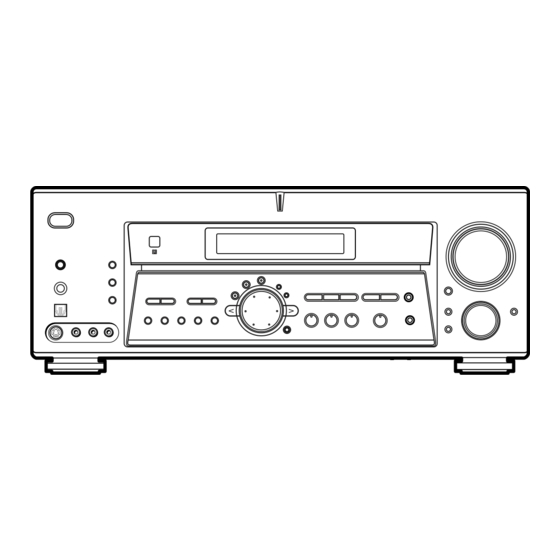
About This Manual The instructions in this manual are for models STR-DE985 and STR-DE885. Check your model number by looking at the lower right corner of the front panel. In this manual, the STR-DE985 is used for illustration purpose unless stated otherwise. Any difference in operation is clearly indicated in the text, for example, “STR-DE985 only”. -
Page 5: List Of Button Locations And Reference Pages
List of Button Locations and Reference Pages How to use this page Use this page to find the location of buttons that are mentioned in the text. Main unit ALPHABETICAL ORDER 0 – 9 2CH wl (31, 32) 2ND ROOM (STR-DE985 only) wd (28) A –... -
Page 6: Hooking Up The Components
Hooking Up the Components Required cords The following cords A – H are required when you hook up the components (pages 8–15). A Audio cord (not supplied) White (L) Red (R) B Audio/video cord (not supplied) Yellow (video) White (L/audio) Red (R/audio) C Video cord (not supplied) Yellow (video) -
Page 7: Antenna Hookups
Antenna hookups DIGITAL OPTICAL SACD MD/DAT MD/DAT TV/SAT DVD/LD COAXIAL SIGNAL GND PHONO CD/SACD * The shape of the connector varies depending on the area code. Notes on antenna hookups • To prevent noise pickup, keep the AM loop antenna away from the receiver and other components. -
Page 8: Audio Component Hookups
Audio component hookups STR-DE985 only OPTICAL MD/DAT MD/DAT TV/SAT DVD/LD COAXIAL CD or SACD player Note on audio component hookups If your turntable has a ground wire, connect it to the U SIGNAL GND terminal. MD or DAT deck INPUT OUTPUT LINE Turntable DIGITAL... - Page 9 STR-DE885 only Turntable DIGITAL OPTICAL SACD TAPE TAPE TV/SAT DVD/LD COAXIAL SIGNAL GND PHONO CD/SACD OUTPUT LINE CD or SACD player Note on audio component hookups If your turntable has a ground wire, connect it to the U SIGNAL GND terminal. MD or Tape deck INPUT OUTPUT LINE...
-
Page 10: Video Component Hookups
Video component hookups TV or satellite tuner DIGITAL OPTICAL SACD MD/DAT MD/DAT TV/SAT DVD/LD COAXIAL To the front panel PHONO CD/SACD Camcorder or video game * For STR-DE985, you can display the SURR, LEVEL, EQ, SET UP and CUSTOMIZE parameters and selected sound field by pressing ON SCREEN. -
Page 11: Digital Component Hookups
For 6.1 channel surround sound, you will also need a surround back speaker (STR-DE985) or refer page 18 (STR-DE885). You can also connect an LD player with an RF OUT jack via an RF demodulator, like the Sony MOD-RF1 (not supplied). Note You cannot connect an LD player’s DOLBY DIGITAL RF OUT jack directly to this unit’s digital input jacks. - Page 12 Connect the digital output jacks of your MD or DAT deck to the receiver’s digital input jack and connect the digital input jacks of your MD or DAT deck to the receiver’s digital output jack. These connections allow you to make digital recordings of TV broadcasts, etc. DIGITAL OPTICAL SACD...
-
Page 13: Multi Channel Input Hookups
Multi channel input hookups Although this receiver incorporates a multi channel decoder, it is also equipped with multi channel input jacks. These connections allow you to enjoy multi channel software encoded in formats other than Dolby Digital and DTS. If your DVD player is equipped with multi channel output jacks, you can connect them directly to the receiver to enjoy the sound of the DVD player’s multi channel decoder. -
Page 14: Other Hookups
MULTI CH IN 1 2ND ROOM PRE OUT 2ND ROOM OUT* • If you have a Sony CD changer with a COMMAND MODE selector If your CD changer’s COMMAND MODE selector can be set to CD 1, CD 2, or CD 3, be sure to set the command mode to “CD 1”... - Page 15 S-LINK CONTROL S hookup (STR-DE985 only) If you have a S-LINK CONTROL S- compatible Sony TV, satellite tuner, monitor, DVD player or VCR, use an audio/video/ control S connecting cord (supplied) or a monaural mini-plug cord (supplied) to connect the CTRL S (STATUS) IN (for TV, satellite tuner, or monitor) or OUT (for VCR, etc.) jack...
-
Page 16: Connecting The Ac Power Cord
Other hookups (continued) Connecting the AC power cord SURROUND CENTER SURR BACK – – – IMPEDANCE USE 8 – 16Ω AC OUTLET AC OUTLET * The configuration, shape, and number of AC outlets vary according to the model and country to which the receiver is shipped. -
Page 17: Hooking Up And Setting Up The Speaker System
Hooking Up and Setting Up the Speaker System Speaker system hookups Required cords A Speaker cords (not supplied) (–) B Monaural audio cord (not supplied) Black Front speaker A Front speaker A S–VIDEO CTRL S CTRL S S–VIDEO S–VIDEO S–VIDEO CTRL S IN COMPONENT VIDEO VIDEO OUT... - Page 18 Speaker system hookup (continued) Notes • Twist the stripped ends of the speaker cords about 10 mm (2/3 inch). Be sure to match the speaker cord to the appropriate terminal on the components: + to + and – to –. If the cords are reversed, the sound will be distorted and will lack bass.
-
Page 19: Performing Initial Setup Operations
Performing initial setup operations Once you have hooked up the speakers and turned on the power, clear the receiver’s memory. Then specify the speaker parameters (size, position, etc.) and perform any other initial setup operations necessary for your system. To check the audio output during settings (to set up while outputting the sound), check the connection (page 25). -
Page 20: Specifying The Speaker Parameters
Multi channel surround setup (continued) When placing surround speakers to your side 45° When placing surround speakers behind you 45° When you set up the surround back speaker, set the speaker at least 1 meter behind the listening position. It is recommended to place the speaker at an equal distance from the surround left and right speakers. - Page 21 x Front speaker size (FRONT) • If you connect large speakers that will effectively reproduce bass frequencies, select “LARGE”. Normally, select “LARGE”. • If the sound is distorted, or you feel a lack of surround effects when using multi channel surround sound, select “SMALL”...
- Page 22 Multi channel surround setup (continued) x Sub woofer selection (SUB WOOFER) • If you connect a sub woofer, select “YES”. • If you do not connect a sub woofer, select “NO”. This activates the bass redirection circuitry and outputs the LFE signals from other speakers.
- Page 23 The surround/surround back speaker position parameter is designed specifically for implementation of the Digital Cinema Sound modes with virtual elements. With the Digital Cinema Sound modes, speaker position is not as critical as other modes. All modes with virtual elements were designed under the premise that the surround speaker would be located behind the listening position, but presentation remains fairly consistent even with the surround speakers...
- Page 24 Multi channel surround setup (continued) The receiver allows you to input the speaker position in terms of distance. However, it is not possible to set the center speaker further than the front speakers. Also, the center speaker cannot be set more than 1.5 meters (5 feet) closer than the front speakers.
-
Page 25: Checking The Connections
Adjusting the speaker level Use the remote while seated in your listening position to adjust the level of each speaker. Note The receiver incorporates a new test tone with a frequency centered at 800 Hz for easier speaker level adjustment. Press ?/1 to turn on the receiver. -
Page 26: Basic Operations
Basic Operations Selecting the component FUNCTION control Turn FUNCTION control to select the component you want to use. To select Rotate to light VIDEO 1* or VIDEO 2* Camcorder or VIDEO 3* video game DVD or LD player DVD/LD* TV or satellite tuner TV/SAT* Tape deck TAPE (STR-DE985) - Page 27 MULTI/2CH ANALOG DIRECT Press MULTI/2CH ANALOG DIRECT to enjoy the audio source connected to the MULTI CH IN jacks or analog 2 channel input jacks. Only volume control and the front speaker balance can be adjusted when set to 2CH ANALOG DIRECT. When set to MULTI CH DIRECT , you can adjust balance and level of all the speakers.
-
Page 28: Listening To The Sound In Another Room
Listening to the sound in another room (STR-DE985 only) Press 2ND ROOM repeatedly to select the analog audio signals for output to a stereo amplifier in another room. For details on the connection, see page 15. Each time you press the button, the audio source changes cyclically as follows: t TAPE t MD/DAT t SOURCE*... -
Page 29: Enjoying Surround Sound
In collaboration with Sony Pictures Entertainment, Sony measured the sound environment of their studios and integrated the data of the measurement and Sony’s own DSP (Digital Signal Processor) technology to develop “Digital Cinema Sound”. In a home theater, “Digital Cinema Sound” simulates an ideal movie theater sound environment based on the preference of the movie director. - Page 30 CINEMA STUDIO EX A (Cinema Studio EX A) Reproduces the sound characteristics of the Sony Pictures Entertainment “Cary Grant Theater” cinema production studio. This is a standard mode, great for watching most any type of movie. x CINEMA STUDIO EX B (Cinema Studio...
- Page 31 Selecting other sound fields Press MODE (SOUND FIELD) repeatedly to select the sound field you want. The current sound field is indicated in the display. x NORMAL SURROUND (Normal Surround) Software with multi channel surround audio signals is played back according to the way it was recorded.
-
Page 32: Using Only The Front Speakers (2 Channel Stereo)
Selecting a sound field (continued) When headphones are connected You can select the following sound fields only. x HEADPHONE (2CH) (Headphone 2CH) Output the sound in 2 channel (stereo). Standard 2 channel (stereo) sources completely bypass the sound field processing. Multi channel surround formats are downmixed to 2 channel. -
Page 33: Selecting The Surround Back Decoding Mode (Surr Back Decoding)
Selecting the surround back decoding mode (SURR BACK DECODING) You can select the surround back decoding mode to reproduce the surround back signal and enjoy 6.1 channel surround sound. Press SURR BACK DECODING to select the surround back decoding mode. “SB DECODING XXXXXX”... -
Page 34: Understanding The Multi Channel Surround Displays
Understanding the multi channel surround displays OPTCOAXMULTI CH IN 1 2 ; DTS MPEG SP.OFF D.RANGE 1 OPT: Lights up when the source signal is a digital signal being input through the OPTICAL terminal. 2 COAX: Lights up when the source signal is a digital signal being input through the COAXIAL terminal. -
Page 35: Customizing Sound Fields
0 Tuner indicators: Lights up when using the receiver to tune in radio stations, etc. See pages 40–41 for tuner operations. qa SLEEP: Lights up when sleep timer is activated. qs EQ: Lights up when the equalizer functions. qd D.RANGE: Lights up when dynamic range compression is activated. - Page 36 Customizing sound fields (continued) Initial settings Parameter Initial setting EFFECT (depends on the sound field) WALL S__I__H Midpoint REVERB S__I__L Midpoint FRONT REVERB STD (STANDARD) SCREEN DEPTH VIR. SPEAKERS 1) You can set this parameter only when you set “MENU EXPAND” to “ON” in the CUSTOMIZE menu (page 44).
- Page 37 Adjusting the level parameters The LEVEL menu contains parameters that let you adjust the balance and volumes of each speaker. The settings are applied to all sound fields. Start playing a program source encoded with multi channel surround sound. Press LEVEL. The button lights up and the first parameter is displayed.
-
Page 38: Adjusting The Equalizer
Customizing sound fields (continued) Dynamic range compressor (D. RANGE COMP. XXX) Lets you compress the dynamic range of the sound track. This may be useful when you want to watch movies at low volumes late at night. We recommend using the “MAX” setting. •... - Page 39 Surround speaker bass adjustment (Gain/Frequency*) Lets you adjust the gain and frequency of bass. Surround speaker treble adjustment (Gain/Frequency*) Lets you adjust the gain and frequency of treble. Surround back speaker bass adjustment (Gain/Frequency*) Lets you adjust the gain and frequency of bass. Surround back speaker treble adjustment (Gain/Frequency*) Lets you adjust the gain and frequency of...
-
Page 40: Receiving Broadcasts
Receiving Broadcasts Before receiving broadcasts, make sure you have connected FM and AM antennas to the receiver (page 7). Direct tuning You can enter a frequency of the station you want directly by using the numeric buttons on the supplied remote. For details on the buttons used in this section, see pages 48–57 for remote RM-PG411 and pages 48–55 for remote RM-PP411. -
Page 41: Preset Tuning
Preset tuning After you have tuned in stations using Direct Tuning or Automatic Tuning, you can preset them to the receiver. Then you can tune in any of the stations directly by entering its 2-character preset code using the supplied remote. -
Page 42: Other Operations
Other Operations Naming preset stations and program sources You can enter a name (index name) of up to 8 characters for preset stations and program sources. These names (for example, “VHS”) appear in the receiver’s display when a station or program source is selected. Note that no more than one name can be entered for each preset station or program source. -
Page 43: Using The Sleep Timer
Notes • You cannot record a digital audio signal using a component connected to the analog TAPE OUT or MD/DAT OUT jacks (STR-DE985) or the analog MD/TAPE OUT jacks (STR-DE885). To record a digital audio signal, connect a digital component to the DIGITAL MD/DAT OUT jacks (STR-DE985) or the DIGITAL MD/TAPE OUT jacks (STR- DE885). -
Page 44: Adjustments Using The Customize Button
Adjustments using the CUSTOMIZE button The CUSTOMIZE button allows you to make the following adjustments. Press CUSTOMIZE. Press to select the parameter you want to adjust. Turn the jog dial to select the setting you want. The setting is entered automatically. Repeat steps 2 and 3 until you have set all of the parameters that follow. - Page 45 Lets you adjust the position of the on-screen display vertically. x Selecting the command mode of the remote (COMMAND MODE XXX) Lets you select the command mode of the remote. Change the command mode when you use 2 Sony receivers in the same room.
-
Page 46: Control A1 Control System
The CONTROL A1 control system has been updated to the CONTROL A1 which is the standard system in the Sony 300 disc CD changer and other recent Sony components. Components with CONTROL A1 jacks are compatible with components with CONTROL A1 , and can be connected to each other. -
Page 47: Basic Functions
In this case, use the connecting cord for your connection. When using a commercially available cord, use a monaural mini-plug cord less than 2 meters long, with no resistance (such as the Sony RK-G69HG). Basic Functions The CONTROL A1... -
Page 48: Operations Using The Remote Rm
Operations Using the Remote RM-PG411 and RM-PP411 You can use the remote RM-PG411 (STR- DE985 only) or RM-PP411 (STR-DE885 only) to operate the components in your system. Before you use your remote Inserting batteries into the remote Insert R6 (size-AA) batteries with the + and – properly oriented in the battery compartment. - Page 49 CD player/ video components on or VCD player/ off. LD player/ DVD player/ MD deck/ DAT deck SYSTEM Receiver/TV/ Turns off the receiver and STANDBY VCR/Satellite other Sony audio/video (Press tuner/CD components. AV ?/1 player/VCD and ?/1 player/LD player/ at the...
- Page 50 LD player/ MD deck/ DAT deck/ Tape deck DISC CD player/ VCD player * Only for Sony TVs with the picture-in-picture function. Remote Button ./> VCR/ Function Select track numbers Changes the sound to m/M CD player/ Multi channel TV Sound.
- Page 51 Remote Operations Function Button RETURN/ VCD player/ Returns to the previous EXIT LD player/ menu. DVD player Satellite Exits the menu. tuner SUBTITLE DVD player Changes the subtitles. CLEAR DVD player Press if you made a mistake when you press the number button or press to return to the continuous play etc.
-
Page 52: Selecting The Mode Of The Remote
Furthermore, you can also program the remote for Sony components that the remote is unable to control. Note that the remote can only control components that accept infrared wireless control signals. - Page 53 Use the numeric codes in the tables below to control non-Sony components and also Sony components that the remote is normally unable to control. Since the remote signal that a component accepts differs depending on the...
- Page 54 Programming the remote (continued) To control a CD player Maker SONY DENON KENWOOD MAGNAVOX MARANTZ ONKYO PANASONIC PHILIPS PIONEER TECHNICS YAMAHA To control a DAT deck Maker SONY PIONEER To control an MD deck Maker SONY DENON KENWOOD To control a tape deck...
-
Page 55: Learning The Commands Of Your Components
To control a DVD player Maker Code(s) SONY 401, 402, 403 PANASONIC 406, 408 PHILIPS PIONEER TOSHIBA DENON To control a TV Maker Code(s) SONY DAEWOO 504, 505, 506, 507, 515, FISHER GOLDSTAR 503, 511, 512, 515, 534, GRUNDIG 517, 534... - Page 56 Learning the commands of your components (continued) Press the appropriate button on the remote control to be learned to send the remote button code. Lightly pressing the button once should be sufficient. If learning is completed successfully, the indicator slowly flashes twice and the remote automatically exits the learning mode.
-
Page 57: Performing Several Commands In Sequence Automatically (Macro Play)
Performing several commands in sequence automatically (Macro Play) (RM-PG411 only) The Macro Play function lets you link several IR codes in a sequential order as a single command. The remote provides 2 macro lists (M1 and M2). You can specify up to 10 IR codes for each macro list. -
Page 58: Additional Information
If you have any question or problem concerning your receiver, please consult your nearest Sony dealer. Troubleshooting If you experience any of the following... - Page 59 There is no sound from one of the front speakers. Connect a pair of headphones to the PHONES jack to verify that sound is output from the headphones (page 27). If only one channel is output from the headphones, the component may not be connected to the receiver correctly.
- Page 60 Troubleshooting (continued) To connect an LD player via an RF demodulator. Connect the LD player to the RF demodulator, then connect the RF demodulator’s optical or coaxial digital output to the receiver’s jack. When making this connection, be sure to set INPUT MODE manually (page 26).
-
Page 61: Specifications
Specifications AUDIO POWER SPECIFICATIONS POWER OUTPUT AND TOTAL HARMONIC DISTORTION: With 8 ohm loads, both channels driven, from 20 – 20,000 Hz; rated 100 watts per channel minimum RMS power, with no more than 0.09 % total harmonic distortion from 250 milliwatts to rated output (Models of area code U only). - Page 62 Specifications (continued) Harmonic distortion at 1 kHz Mono: Stereo: Separation Frequency response Selectivity AM tuner section Tuning range Models of area code U, CA With 10-kHz tuning scale: 530 – 1710 kHz With 9-kHz tuning scale: 531 – 1710 kHz Antenna Intermediate frequency Usable sensitivity...
-
Page 63: Tables Of Settings Using Surr, Level, Eq, Set Up And Customize Buttons
Tables of settings using SURR, LEVEL, EQ, SET UP and CUSTOMIZE buttons You can make various settings using the LEVEL, SURR, EQ, SET UP and CUSTOMIZE buttons, jog dial, and cursor buttons. The tables below show each of the settings that these buttons can make. Press Press to select... - Page 64 Tables of settings using SURR, LEVEL, EQ, SET UP and CUSTOMIZE buttons (continued) Press Press FRONT BASS GAIN FRONT BASS FREQUENCY FRONT MID GAIN FRONT MID FREQUENCY FRONT TREBLE GAIN FRONT TREBLE FREQUENCY CENTER BASS GAIN CENTER BASS FREQUENCY CENTER MID GAIN CENTER MID FREQUENCY CENTER TREBLE GAIN CENTER TREBLE FREQUENCY...
- Page 65 Press Press to select SET UP FRONT CENTER SURROUND SURR BACK SUB WOOFER SURR POSI. SURR HEIGHT SURR BACK HGT. FRONT XX.X feet CENTER XX.X feet SURROUND XX.X feet SURR BACK XX.X feet SUB WOOFER XX.X feet DISTANCE UNIT FRONT SP > XXX Hz CENTER SP >...
-
Page 66: Adjustable Parameters For Each Sound Field
Adjustable parameters for each sound field The adjusted SURR and EQ parameters are stored in each sound field. The adjusted LEVEL parameters are applied to all the sound fields. 2CH STEREO AUTO DECODING NORMAL SURROUND CINEMA STUDIO EX A CINEMA STUDIO EX B CINEMA STUDIO EX C MONO MOVIE STEREO MOVIE... - Page 67 < FRONT CENTER SURR L 2CH STEREO AUTO DECODING NORMAL SURROUND CINEMA STUDIO EX A CINEMA STUDIO EX B CINEMA STUDIO EX C MONO MOVIE STEREO MOVIE D. CONCERT HALL A D. CONCERT HALL B CHURCH OPERA HOUSE JAZZ CLUB DISCO / CLUB LIVE CONCERT ARENA...
- Page 68 Adjustable parameters for each sound field (continued) 2CH STEREO AUTO DECODING NORMAL SURROUND CINEMA STUDIO EX A CINEMA STUDIO EX B CINEMA STUDIO EX C MONO MOVIE STEREO MOVIE D. CONCERT HALL A D. CONCERT HALL B CHURCH OPERA HOUSE JAZZ CLUB DISCO / CLUB LIVE CONCERT...
- Page 69 < < BASS GAIN 2CH STEREO AUTO DECODING NORMAL SURROUND CINEMA STUDIO EX A CINEMA STUDIO EX B CINEMA STUDIO EX C MONO MOVIE STEREO MOVIE D. CONCERT HALL A D. CONCERT HALL B CHURCH OPERA HOUSE JAZZ CLUB DISCO / CLUB LIVE CONCERT ARENA STADIUM...
- Page 70 Adjustable parameters for each sound field (continued) 2CH STEREO AUTO DECODING NORMAL SURROUND CINEMA STUDIO EX A CINEMA STUDIO EX B CINEMA STUDIO EX C MONO MOVIE STEREO MOVIE D. CONCERT HALL A D. CONCERT HALL B CHURCH OPERA HOUSE JAZZ CLUB DISCO / CLUB LIVE CONCERT...
- Page 71 Sony Corporation Printed in Malaysia...