Sony STR-DH810 Operating Instructions Manual
Multi channel av receiver
Hide thumbs
Also See for STR-DH810:
- Service manual (84 pages) ,
- Quick setup manual (2 pages) ,
- Specifications (2 pages)

Related Manuals for Sony STR-DH810


Summary of Contents for Sony STR-DH810
- Page 1 Multi Channel AV Receiver Operating Instructions STR-DH810 ©2010 Sony Corporation 4-168-075-11(1)
-
Page 2: Important Safety Instructions
The model and serial numbers are located on the rear of the unit. Record these numbers in the space provided below. Refer to them whenever you call upon your Sony dealer regarding this product. Model No. Serial No. This symbol is intended to alert the user to the presence of uninsulated “dangerous voltage”... - Page 3 13)Unplug this apparatus during lightning storms or when unused for long periods of time. 14)Refer all servicing to qualified service personnel. Servicing is required when the apparatus has been damaged in any way, such as power-supply cord or plug is damaged, liquid has been spilled or objects have fallen into the apparatus, the apparatus has been exposed to rain or moisture, does not operate normally, or has been dropped.
- Page 4 Notice for customers: The following information is only applicable to equipment sold in countries applying EU Directives. The manufacturer of this product is Sony Corporation, 1-7-1 Konan Minato-ku Tokyo, 108-0075 Japan. The Authorized Representative for EMC and product safety is Sony Deutschland GmbH, Hedelfinger Strasse 61, 70327 Stuttgart, Germany.
-
Page 5: About This Manual
“x.v.Colour (x.v.Color)” and “x.v.Colour (x.v.Color)” logo are trademarks of Sony Area code Corporation. “BRAVIA” is a trademark of Sony Corporation. “S-AIR” and its logo are trademarks of Sony Corporation. “PLAYSTATION” is a trademark of Sony Computer Entertainment Inc. ) technology. -
Page 6: Table Of Contents
Table of Contents About This Manual...5 Supplied accessories...7 Description and location of parts...8 Connections 1: Installing the speakers ...17 2: Connecting the speakers ...19 3: Connecting the TV ...21 4a: Connecting the audio components...23 4b: Connecting the video components ...24 5: Connecting the antennas (aerials)...32 6: Inserting the wireless transmitter/ transceiver...32... -
Page 7: Supplied Accessories
Advanced Operations Switching between digital and analog audio (INPUT MODE) ... 69 Enjoying the sound/images from other inputs... 69 Enjoying sound/images from the components connected to the DIGITAL MEDIA PORT... 71 Using a bi-amplifier connection... 71 Using the setting menu... 72 Using the Remote Programming the remote... -
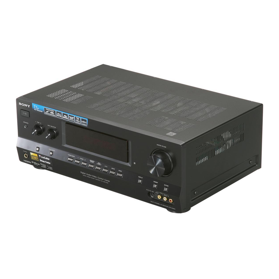
Page 8: Description And Location Of Parts
Description and location of parts Front panel A ?/1 (on/standby) (page 34, 48, 55) B TONE +/–, TONE MODE (page 81) C INPUT SELECTOR (page 43) D Display (page 9) E Remote sensor Receives signals from remote commander. F DIMMER (page 85) G MASTER VOLUME (page 42, 43) H MUTING (page 43) I VIDEO 2 IN jacks (page 30) - Page 9 Indicators on the display PLII x z ANALOG SW RH Indicator and explanation A SW Lights up when the audio signal is output from the SUBWOOFER jack. B Dolby Pro Logic indicators Lights up one of the respective indicators when the receiver performs Dolby Pro Logic processing.
- Page 10 Indicator and explanation J BI-AMP Lights up when surround back speakers selection is set to “BI-AMP” (page 71). K SLEEP Lights up when the Sleep Timer is activated (page 45). L LPCM Lights up when the receiver is decoding the Linear PCM signals.
-
Page 11: Rear Panel
Rear panel ANTENNA EZW-T100 MONITOR IN 3 IN 2 IN 1 DMPORT DC5V 0.7A MAX OPTICAL VIDEO VIDEO VIDEO VIDEO MONITOR COMPONENT VIDEO AUDIO AUDIO AUDIO AUDIO AUDIO AUDIO AUDIO ASSIGNABLE (INPUT ONLY) SA-CD/CD/CD-R VIDEO 1 SAT/CATV SUBWOOFER A S-AIR section (page 32) EZW-T100 slot B DMPORT section (page 23) DMPORT jack... - Page 12 TV (page 21, 24). F SPEAKERS section (page 19) Remote commander You can use the supplied remote to operate the receiver and to control the Sony audio/video components that the remote is assigned to operate. You can also program the remote to control non-Sony audio/video components.
-
Page 13: Input Buttons
Selects the component you want to play back or record. When you press any of the input buttons, the receiver turns on. The buttons are initial assigned to control Sony components. Numeric buttons (number 5 Presets or tunes to preset stations. - Page 14 X THEATER (RM-AAP049 only) THEATRE (RM-AAP050 only) Sets the optimal picture settings automatically for watching movies when you connect a Sony TV that is compatible with the THEATER or THEATRE button function (page 59). The following buttons have tactile dots. Use the tactile dots as references when operating the receiver.
- Page 15 To control other Sony components Name Blu-ray disc, DVD player B AV ?/1 Power D Numeric Channel a)c) buttons -/-- , >10 Clear ENTER Enter F Color Menu, buttons guide H TOOLS/ Options OPTIONS menu I MENU/HOME Menu J ./>...
-
Page 16: Inserting Batteries Into The Remote
The following buttons have tactile dots. Use the tactile dots as references when operating the receiver. – number 5, VIDEO 1 – N – PRESET +, TV CH + (RM-AAP049 only), PROG + (RM-AAP050 only), c (RM-AAP050 only) If you press ?/1 (A) and AV ?/1 (B) simultaneously, the receiver and connected components will turn off (SYSTEM STANDBY). -
Page 17: Connections
Connections 1: Installing the speakers This receiver allows you to use a 7.1 channel system (7 speakers and one subwoofer). To fully enjoy theater-like multi channel surround sound requires five speakers (two front speakers, a center speaker, and two surround speakers) and a subwoofer (5.1 channel). - Page 18 • When you connect a 7.1 channel speaker system with two front high speakers, place the front high speakers – at an angle between 22° to 45°. – at least 1 meter (3.3 feet) directly above the front speakers. • When you connect a 6.1 channel speaker system, place the surround back speaker behind the listening position.
-
Page 19: 2: Connecting The Speakers
2: Connecting the speakers Before connecting the cords, be sure to disconnect the AC power cord (mains lead). Center speaker ANTENNA IN 4 IN 3 DMPORT DC5V SAT/ 0.7A MAX CATV OPTICAL OPTICAL VIDEO VIDEO VIDEO VIDEO SURROUND BACK/ FRONT HIGH/ MONITOR AUDIO AUDIO... - Page 20 Notes on the SPEAKERS SURROUND BACK/ FRONT HIGH/BI-AMP/FRONT B terminals connection. • If you connect only one surround back speaker, connect it to L of this terminals. • If you are not using surround back speaker or front high speakers, and you have an additional front speaker system, connect the additional front speaker system to this terminals.
-
Page 21: 3: Connecting The Tv
A Component video cord (not supplied) B Video cord (not supplied) C Optical digital cord (not supplied) D Audio cord (not supplied) E HDMI cable (not supplied) We recommend that you use a Sony HDMI cable. Audio signals Audio/Video ANTENNA... - Page 22 Notes • Be sure to turn on the receiver when the video and audio signals of a playback component are being output to a TV via the receiver. Unless the power is turned on, neither video nor audio signals will be transmitted.
-
Page 23: 4A: Connecting The Audio Components
4a: Connecting the audio components The following illustration shows how to connect a Super Audio CD player, CD player, CD recorder and DIGITAL MEDIA PORT adapter. Before connecting cords, be sure to disconnect the AC power cord (mains lead). Super Audio CD player, CD player, CD recorder... -
Page 24: 4B: Connecting The Video Components
4b: Connecting the video components Components to be connected Connect your video components according to the table below. Component Blu-ray disc player* DVD player* DVD recorder* Satellite tuner*, Cable TV tuner* “PlayStation 3”* Camcorder, video game, etc. * We recommend that you connect your video components via HDMI connection if they have HDMI jacks. - Page 25 AUDIO AUDIO ASSIGNABLE (INPUT ONLY) SA-CD/CD/CD-R SAT/CATV A HDMI cable (not supplied) We recommend that you use a Sony HDMI cable. * See page 21 for the audio connection of TV to the receiver. DVD player, DVD recorder Audio/video signals...
-
Page 26: Notes On Connecting Cables
Standard HDMI cable, 1080p or Deep Colour (Deep Color) images may not be displayed properly. • Sony recommends that you use an HDMI authorized cable or Sony HDMI cable. • We do not recommend using an HDMI-DVI conversion cable. When you connect an... -
Page 27: Connecting A Blu-Ray Disc Player
Connecting a Blu-ray disc player The following illustration shows how to connect a Blu-ray disc player. Video signals EZW-T100 MONITOR IN 3 IN 2 IN 1 DMPORT DC5V 0.7A MAX VIDEO VIDEO VIDEO COMPONENT VIDEO AUDIO AUDIO AUDIO AUDIO AUDIO AUDIO ASSIGNABLE (INPUT ONLY) SA-CD/CD/CD-R... - Page 28 Connecting a DVD player, DVD recorder The following illustration shows how to connect a DVD player or DVD recorder. DVD player, DVD recorder Video signals EZW-T100 MONITOR IN 3 IN 2 IN 1 DMPORT DC5V 0.7A MAX VIDEO VIDEO COMPONENT VIDEO AUDIO AUDIO AUDIO...
- Page 29 Connecting a satellite tuner, cable TV tuner The following illustration shows how to connect a satellite tuner or cable TV tuner. Satellite tuner, Cable TV tuner Video signals EZW-T100 MONITOR IN 3 IN 2 IN 1 DMPORT DC5V 0.7A MAX VIDEO VIDEO VIDEO...
- Page 30 Connecting components with analog video and audio jack The following illustration shows how to connect a component which has analog jacks such as a VCR, DVD recorder, etc. Video signals EZW-T100 MONITOR IN 3 IN 2 IN 1 DMPORT DC5V 0.7A MAX VIDEO VIDEO...
-
Page 31: Function For Conversion Of Video Signals
Function for conversion of video signals The receiver is equipped with a function for converting video signals. Video signals and component video signals can be output as HDMI video signals (HDMI TV OUT jack only). INPUT jack HDMI IN COMPONENT VIDEO IN VIDEO IN : Same type of signal as that of the input signal is output. -
Page 32: 5: Connecting The Antennas (Aerials)
5: Connecting the antennas (aerials) Connect the supplied AM loop antenna (aerial) and FM wire antenna (aerial). Before connecting antennas (aerials), be sure to disconnect the AC power cord (mains lead). FM wire antenna (aerial) (supplied) AM loop antenna (aerial) (supplied) EZW-T100 MONITOR... -
Page 33: 7: Connecting The Ac Power Cord (Mains Lead)
Insert the wireless transmitter. EZW-T100 slot - T 1 E Z W Wireless transmitter Notes • Insert the wireless transmitter with the S-AIR logo facing up. • Insert the wireless transmitter so that the V marks are aligned. • Do not insert other than the wireless transmitter into the EZW-T100 slot. -
Page 34: Preparing The Receiver
Preparing the Receiver Initializing the receiver Before using the receiver for the first time, initialize the receiver by performing the following procedure. This procedure can also be used to return settings you have made to their initial settings. Be sure to use the buttons on the receiver for this operation. -
Page 35: Calibrating The Appropriate Speaker Settings Automatically (Auto Calibration)
Calibrating the appropriate speaker settings automatically (AUTO CALIBRATION) This receiver is equipped with DCAC (Digital Cinema Auto Calibration) Technology which allows you to perform automatic calibration as follows: • Check the connection between each speaker and the receiver. • Adjust the speaker level. •... - Page 36 1: Setting up the Auto Calibration When using surround back speakers AUTO CAL MIC When using front high speakers Optimizer microphone * Be sure to set the speaker pattern to a setting with front high speakers (page 78). Connect the supplied optimizer microphone to the AUTO CAL MIC jack.
- Page 37 2: Performing Auto Calibration SAT/ CATV VIDEO 1 VIDEO 2 SA-CD/ DMPORT TUNER HDMI 1 HDMI 2 HDMI 3 HDMI 4 V/v/B/b MENU < < > MUTING/ Press AMP MENU. Press V/v repeatedly to select “<AUTO CAL>”, then press or b. Press V/v repeatedly to select “A.CAL START”, then press Measurement starts in 5 seconds.
- Page 38 See “When error ENGINEER codes appear” Sets the frequency characteristics to a set that (page 39). matches that of the Sony listening room standard. FRONT REF Adjusts the characteristics of all speakers to match the characteristics of the front speaker.
- Page 39 When error codes appear Check the problem of the error. Display and explanation * : 31 SPEAKERS is set to “SPK OFF”. Set it to others (page 34) and perform the measurement again. * : 32 None of the speakers were detected. Make sure that the optimizer microphone is connected properly and perform the measurement again.
- Page 40 Display and explanation * : 42 The volume of the receiver is out of the acceptable range. Try to perform the measurement when the environment is quiet enough to allow proper measurement. * : 43 The distance and position of a subwoofer cannot be detected.
- Page 41 Perform Auto Calibration and save the measurement results. See “2: Performing Auto Calibration” (page 37) and “3: Confirming/saving the measurement results” (page 38). The measurement results is registered as the position you selected in step 4. Repeat steps 1 to 5 to register another seating position.
-
Page 42: Adjusting The Speaker Levels (Test Tone)
Adjusting the speaker levels (TEST TONE) You can adjust the speaker levels while listening to the test tone from your listening position. SAT/ CATV VIDEO 1 VIDEO 2 SA-CD/ DMPORT TUNER HDMI 1 HDMI 2 HDMI 3 HDMI 4 V/v/B/b MENU <... -
Page 43: Basic Operations
Basic Operations Playback SAT/ CATV VIDEO 1 VIDEO 2 SA-CD/ DMPORT TUNER HDMI 1 HDMI 2 HDMI 3 HDMI 4 V/v/B/b MENU < < > MUTING/ Turn on the connected component. Turn on the receiver. Press one of the input buttons to select the component you want. -
Page 44: Viewing Information On The Display
Naming inputs You can enter a name of up to 8 characters for inputs (except TUNER) and display it on the receiver’s display. This is convenient for labeling the jacks with the names of the connected components. Press one of the input buttons to select the input you want to create an index name for. -
Page 45: Using The Sleep Timer
Using the Sleep Timer You can set the receiver to turn off automatically at a specified time. SAT/ CATV VIDEO 1 VIDEO 2 SA-CD/ DMPORT TUNER HDMI 1 HDMI 2 HDMI 3 HDMI 4 MENU < < > Press AMP, then press SLEEP repeatedly while the power is on. -
Page 46: Tuner Operations
Recording onto a recording media Press one of the input buttons to select the playback component. You can also use INPUT SELECTOR on the receiver. Prepare the playback component for playing. For example, insert the video tape you want to copy into the VCR. Prepare the recording component. -
Page 47: Tuning Into A Station
Tuning into a station automatically (Automatic Tuning) Press TUNER repeatedly to select the FM or AM band. Press TUNING + or TUNING –. Press TUNING + to scan from low to high; press TUNING – to scan from high to low. The receiver stops scanning whenever a station is received. -
Page 48: Presetting Fm/Am Radio Stations
Changing the AM tuning scale (Models of area code U2 only) You can change the AM tuning scale to either 9 kHz or 10 kHz using the buttons on the receiver. TUNING MODE Press ?/1 to turn off the receiver. While holding down TUNING MODE, press ?/1. - Page 49 Press MEMORY. You can also use MEMORY/ENTER on the receiver. “MEM” lights up for a few seconds. Perform steps 5 and 6 before “MEM” goes out. Press the numeric buttons to select a preset number. You can also press PRESET + or PRESET –...
-
Page 50: Using The Radio Data System (Rds)
Press V/v repeatedly to select “NAME IN”, then press The cursor flashes and you can select a character. Press V/v to select a character, then press B/b to move the cursor to the next position. If you made a mistake Press B/b until the character you want to change flashes, then press V/v to select the correct character. -
Page 51: Enjoying Surround Sound
C.ST.EX A (Cinema Studio EX A DCS ) Reproduces the sound characteristics of the Sony Pictures Entertainment “Cary Grant Theater” cinema production studio. This is a standard mode, great for watching almost any type of movie. -
Page 52: Music Mode
C.ST.EX C (Cinema Studio EX C DCS ) Reproduces the sound characteristics of the Sony Pictures Entertainment scoring stage. This mode is ideal for watching musicals or films where orchestra music is featured in the soundtrack. x V.MULTI DIM. (V. Multi... - Page 53 x NEO6 MUS (Neo:6 Music) Performs DTS Neo:6 Music mode decoding. A source recorded in 2 channel format is decoded into 7 channels. This setting is ideal for normal stereo sources such as CDs. When headphones are connected You can only select the following sound fields if the headphones are connected to the receiver.
- Page 54 To turn off the surround effect for movie/music Press SOUND FIELD +/– repeatedly to select “2CH ST.” or “A.F.D. AUTO”. You can also press 2CH/A.DIRECT repeatedly on the receiver to select “2CH ST.” or press A.F.D. repeatedly on the receiver to select “A.F.D.
-
Page 55: Enjoying The Surround Effect At Low Volume Levels (Night Mode)
Enjoying the surround effect at low volume levels (NIGHT MODE) This function allows you to retain a theater like environment at low volume levels. This function can be used with other sound fields. When watching a movie late at night, you will be able to hear the dialog clearly even at a low volume level. -
Page 56: Bravia" Sync Features
“BRAVIA” Sync Features What is “BRAVIA” Sync? “BRAVIA” Sync is compatible with Sony TV, Blu-ray Disc/DVD player, AV amplifier, etc., that is equipped with the Control for HDMI function. By connecting Sony components that are compatible with the “BRAVIA” Sync with an... -
Page 57: Playing Back Components With One-Touch Operation (One-Touch Play)
If your TV is not compatible with the “Control for HDMI-Easy Setting” function V/v/B/b MENU Perform the steps given in “If your TV is compatible with the “Control for HDMI- Easy Setting” function” (page 56). Press AMP MENU. Press V/v repeatedly to select “<HDMI>”, then press Press V/v repeatedly to select “CTRL: or b. -
Page 58: Enjoying The Tv Sound From The Speakers Connected To The Receiver (System Audio Control)
Enjoying the TV sound from the speakers connected to the receiver (System Audio Control) You can enjoy the TV sound from the speakers connected to the receiver by a simple operation. You can operate System Audio Control function using the TV menu. For details, refer to the operating instructions of the TV. -
Page 59: Turning Off The Receiver With The Tv (System Power Off)
Turning off the receiver with the TV (System Power Off) When you turn the TV off by using the POWER button on the TV’s remote, the receiver and the connected components turn off automatically. You can also use the receiver’s remote to turn off the TV. -
Page 60: Enjoying The Tv Sound Via An Hdmi Cable (Audio Return Channel)
Enjoying the TV sound via an HDMI cable (Audio Return Channel) The Audio Return Channel (ARC) function enables the TV outputs the audio signals to the receiver via a HDMI cable connected to the HDMI TV OUT jack. You can enjoy the TV sound from the speakers connected to the receiver without connecting the TV AUDIO IN or TV OPTICAL jacks. - Page 61 Room B S-AIR sub unit (S-AIR receiver) Room A S-AIR main unit (this receiver) S-AIR sub unit (surround amplifier) About environments where S-AIR products (S-AIR main unit and sub unit) are used S-AIR products use a radio frequency of 2.4 GHz. Certain electronic equipment or other factors may cause lost connection or instability in S-AIR reception.
-
Page 62: Setting Up An S-Air Product
Setting up an S-AIR product Before using an S-AIR product, be sure to perform the following settings to establish the sound transmission. • Inserting the wireless transmitter/ transceiver (page 32). • Establishing sound transmission between the S-AIR main unit and S-AIR sub unit (ID setting) (page 62). - Page 63 Pairing the S-AIR main unit with a specific S-AIR sub unit (Pairing operation) To establish sound transmission, you need to set the same ID for your S-AIR main unit and S-AIR sub unit. However, if your neighbors have S-AIR products and their IDs are the same as yours, your neighbors could receive the sound of your S-AIR main unit or vice versa.
-
Page 64: Enjoying The System's Sound In Another Room
Press V/v repeatedly to select the setting you want, then press • START: The S-AIR main unit starts pairing. “SEARCHING” flashes on the display. • CONDITION: You can check the current ID. When the pairing setting is not made, “NO PAIRING” appears on the display. - Page 65 Press V/v repeatedly to select “<S-AIR>”, then press Press V/v repeatedly to select “S-AIR MODE”, then press or b. Press V/v repeatedly to select the setting you want. • PARTY: The S-AIR receiver outputs sound according to the input selected on the S-AIR main unit.
-
Page 66: Changing The Channel For Better Sound Transmission
Changing the channel for better sound transmission If you use multiple wireless systems which sharing the 2.4 GHz band, such as wireless LAN or Bluetooth, the transmission of S-AIR products or other wireless systems may be unstable. In this case, the transmission may be improved by changing the following “RF CHANGE”... -
Page 67: Stabilizing S-Air Reception
Stabilizing S-AIR reception Check the following when S-AIR reception is poor or unstable. – Confirm the wireless adapters are inserted correctly (page 32). – Confirm that the S-AIR IDs of the S-AIR main unit and sub unit are the same (page 62). -
Page 68: Enjoying The S-Air Receiver While The S-Air Main Unit Is In Standby Mode
Enjoying the S-AIR receiver while the S-AIR main unit is in standby mode (For the S-AIR receiver only (not supplied)) You can enjoy the S-AIR receiver while the S-AIR main unit is in standby mode by setting “S-AIR STBY” to “STBY ON”. V/v/B/b MENU Press AMP MENU. -
Page 69: Advanced Operations
Advanced Operations Switching between digital and analog audio (INPUT MODE) When you connect components to both digital and analog input jacks on the receiver, you can fix the audio input mode to either of them, or switch from one to the other, depending on the type of material you intend to watch. - Page 70 Assigning input jacks Assignable input jacks Video COMPONENT1 COMPONENT2 COMPONENT3 HDMI1 HDMI2 HDMI3 HDMI4 COMPOSITE NONE Audio BD OPT SAT OPT DVD COAX ANALOG * Initial setting Notes • You cannot assign optical signals from an input source to the optical input jacks on the receiver. •...
-
Page 71: Enjoying Sound/Images From The Components Connected To The Digital Media Port
Enjoying sound/images from the components connected to the DIGITAL MEDIA PORT The DIGITAL MEDIA PORT (DMPORT) allows you to enjoy sound/images from a portable audio source or computer by connecting a DIGITAL MEDIA PORT adapter. The DIGITAL MEDIA PORT adapters are available for purchase depending on the area. -
Page 72: Using The Setting Menu
Using the setting menu By using the setting menus, you can make various adjustments to customize the receiver. V/v/B/b RETURN/ EXIT O MENU < < Press AMP MENU. Press V/v repeatedly to select the menu you want. Press or b to enter the menu. -
Page 73: Overview Of The Menus
Overview of the menus The following options are available in each menu. For details, see the page in the parentheses. Menu Parameters [Display] [Display] AUTO CAL Starts Auto Calibration [<AUTO CAL>] [A.CAL START] (page 40) Calibration type [CAL TYPE] Position [POSITION] Naming position [NAME IN]... - Page 74 Menu Parameters [Display] [Display] SPEAKER Speaker pattern [<SPEAKER>] [SP PATTERN] (page 78) Front speakers size [FRT SIZE] Center speaker size [CNT SIZE] Surround speakers size [SUR SIZE] Front high speakers size [FH SIZE] Surround back speaker assign [SB ASSIGN] Front left speaker distance [FL DIST.] Front right speaker distance [FR DIST.]...
- Page 75 Menu Parameters [Display] [Display] Distance unit [DIST. UNIT] Front speaker crossover frequency [FRT CROSS] Center speaker crossover frequency [CNT CROSS] Surround speaker crossover frequency [SUR CROSS] Front high speaker crossover frequency [FH CROSS] SURROUND Sound field selection [<SURROUND>] [S.F. SELECT] (page 81) Effect level [EFFECT]...
- Page 76 Menu Parameters [Display] [Display] HDMI Control for HDMI [<HDMI>] [CTRL: HDMI] (page 83) HDMI Pass through [PASS THRU] Setting HDMI audio input [AUDIO OUT] Subwoofer level for HDMI [SW LEVEL] Subwoofer Low Pass Filter for HDMI [SW L.P.F.] Audio Return Channel [ARC] SYSTEM Brightness of the display...
- Page 77 LEVEL menu You can adjust the level of each speaker. These settings are applied to all sound fields. x TEST TONE Lets you adjust the speaker levels while listening to the test tone from your listening position. • OFF The test tone is turned off. •...
- Page 78 SPEAKER menu You can set the size and distance of the speakers connected to this receiver. x SP PATTERN Lets you set the number of speakers connected to this receiver. It should be synchronize with the speakers settings. For example: Speaker Front Front left/...
- Page 79 x FRT SIZE • LARGE If you connect large speakers that will effectively reproduce bass frequencies, select “LARGE”. Normally, select “LARGE”. However, if you have selected a speaker pattern without subwoofer, the front speakers are automatically set to “LARGE”. • SMALL If the sound is distorted, or you feel a lack of surround effects when using multi channel surround sound, select “SMALL”...
- Page 80 The “LARGE” and “SMALL” settings for each speaker determine whether the internal sound processor will cut the bass signal from that channel. When the bass is cut from a channel, the bass redirection circuitry sends the corresponding bass frequencies to the subwoofer or other “LARGE” speakers.
- Page 81 x DIST. UNIT Lets you select the unit of measure for setting distances. • METER The distance is displayed in meters. • FEET The distance is displayed in feet. x FRT CROSS Lets you set the bass crossover frequency of the front speakers that have been set to “SMALL”...
-
Page 82: Audio Menu
AUDIO menu You can make settings for the audio to suit your preference. x A/V SYNC Lets you delay the output of audio to minimize the time gap between audio output and visual display. You can adjust from 0 ms to 300 ms in 10 ms steps. -
Page 83: Video Menu
When the TV is turned on while the receiver is in the standby mode, the receiver outputs HDMI signals from the receiver’s HDMI TV OUT jack. Sony recommends this setting if you use a TV that is compatible with “BRAVIA” Sync. This setting saves power in the standby mode compared with the “ON”... -
Page 84: Audio Out
x AUDIO OUT Lets you set the HDMI audio output from the playback component connected to the receiver via an HDMI connection. • AMP The HDMI audio signals from the playback component are only output to the speakers connected to the receiver. Multi channel sound can be played back as it is. -
Page 85: System Menu
Furthermore, you can also program the remote for Sony components that the remote is unable to control. Note that the remote can only control components that accept infrared wireless control signals. -
Page 86: Other Components
Use the numeric codes in the tables below to control non-Sony components and also Sony components that the remote is normally unable to control. Since the remote signal that a... - Page 87 To control a CD player Maker Code(s) SONY 101, 102, 103 DENON 104, 123 105, 106, 107 KENWOOD 108, 109, 110 MAGNAVOX 111, 116 MARANTZ ONKYO 112, 113, 114 PANASONIC PHILIPS PIONEER TECHNICS 115, 118, 119 YAMAHA 120, 121, 122...
- Page 88 To control a DVD/VCR COMBO Maker Code(s) SONY To control a DVD/HDD COMBO Maker Code(s) SONY 401, 402, 403 To control a TV Maker Code(s) SONY 501, 502 AIWA 501, 536, 539 AKAI CENTURION CORONADO CURTIS-MATHES 503, 551, 566, 567...
- Page 89 SHARP 748, 749 TOSHIBA 747, 756 ZENITH * If an AIWA VCR does not work even though you enter the code for AIWA, enter the code for Sony instead. To control a satellite tuner (box) Maker Code(s) SONY 801, 802, 803, 804,...
-
Page 90: Clearing All The Contents Of The Remote's Memory
“Cinema Studio Reverberation” reproduces the sound characteristics of state-of-the-art dubbing theaters and recording studios, including Sony Pictures Entertainment’s dubbing studios. There are three modes, A/B/ C, available according to the studio type. x Component video... - Page 91 Digital Cinema Sound (DCS) A unique sound reproduction technology for home theater developed by Sony, in cooperation with Sony Pictures Entertainment, for enjoying the exciting and powerful sound of movie theaters at home. With this “Digital Cinema Sound”...
-
Page 92: Dolby Truehd
x Dolby TrueHD Dolby TrueHD is Dolby’s lossless audio technology developed for high-definition optical discs. Dolby TrueHD audio is bit-for- bit identical to the original studio masters and provides supreme-quality audio up to 8 channel at 96 kHz/24 bit and up to 6 channel at 192 kHz/24 bit. -
Page 93: Precautions
(x.v.Color) x.v.Colour (x.v.Color) is a more familiar term for the xvYCC standard proposed by Sony, and is a trademark of Sony. xvYCC is an international standard for color space in video. This standard can express a wider colour range than the currently used broadcast standard. - Page 94 S-AIR product(s). – There is an iron divider/door or furniture/ electric product made of fireproof glass, metal, etc., between the S-AIR product(s). If you have any questions or problems concerning your receiver, please consult your nearest Sony dealer.
-
Page 95: Troubleshooting
Troubleshooting If you experience any of the following difficulties while using the receiver, use this troubleshooting guide to help you remedy the problem. Audio There is no sound, no matter which component is selected, or only a very low-level sound is heard. •... - Page 96 The left and right sounds are unbalanced or reversed. • Check that the speakers and components are connected correctly and securely. • Adjust the level parameters using the LEVEL menu. There is severe hum or noise. • Check that the speakers and components are connected securely.
- Page 97 Video There is no picture or an unclear picture appears on the TV screen or monitor. • Select the appropriate input using the input buttons. • Set your TV to the appropriate input mode. • Move your audio components away from the TV.
- Page 98 HDMI The source sound input to the HDMI jack is not output from the receiver or the TV speaker. • Check the HDMI connection (page 24). • You cannot listen to the Super Audio CD by connecting HDMI. • Depending on the playback component, you may need to set up the component.
- Page 99 S-AIR function S-AIR connection is not established (sound transmission is not established), e.g., the indicator of the S-AIR sub unit turns off, flashes, or turns red. • If you use another S-AIR main unit, place it more than 8 meters (26 feet) away from this S-AIR main unit.
-
Page 100: Error Messages
If the problem persist Consult your nearest Sony dealer. Note that if service personnel changes some parts during repair, these parts may be retained. In the event of a problem with S-AIR function,... -
Page 101: Specifications
Reference sections for clearing the receiver’s memory To clear All memorized settings Customized sound fields Specifications AUDIO POWER SPECIFICATIONS page 34 POWER OUTPUT AND TOTAL page 55 HARMONIC DISTORTION: (Models of area code U2 only) With 8 ohm loads, both channels driven, from 20 –... - Page 102 Frequency response Analog 10 Hz – 70 kHz, +0.5/–2 dB (with sound field and equalizer bypassed) Input Analog Sensitivity: 500 mV/ 50 kohms : 96 dB (A, 500 mV Digital (Coaxial) Impedance: 75 ohms S/N: 100 dB (A, 20 kHz LPF) Digital (Optical) S/N: 100 dB (A, 20 kHz LPF) Output (analog)
-
Page 103: Index
Index Numerics 2 Channel Stereo 51 5.1 channel 17 A.F.D. mode 51 Analog Direct 51 Audio Return Channel (ARC) 60 AUTO CALIBRATION 35 BI-AMP 80 Bi-amplifier connection 71 Blu-ray disc player connecting 27 Cable TV tuner connecting 29 Camcorder connecting 30 Clear remote 90 DIGITAL MEDIA PORT... - Page 104 Sony Corporation Printed in Malaysia...