
Related Manuals for Sony STR-DE575


Summary of Contents for Sony STR-DE575
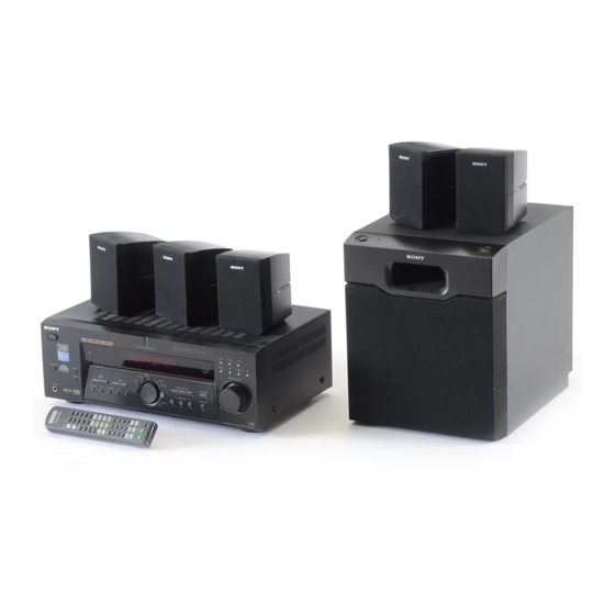
- Page 1 4-235-739-12(1) FM Stereo FM-AM Receiver Operating Instructions STR-DE575 STR-K502 2001 Sony Corporation...
- Page 2 The model and serial numbers are located on the rear of the unit. Record the serial number in the space provided below. Refer to them whenever you call upon your Sony dealer regarding this product. Model No. STR-DE575/K502 Serial No. For customers in Canada...
-
Page 3: Table Of Contents
About This Manual The instructions in this manual are for the STR-DE575 and STR-K502. Check your model number by looking at the lower right corner of the front panel or lower right corner of the remote. In this manual, the STR-DE575 and the remote commander RM-U305 are used for illustration purposes unless stated otherwise. -
Page 4: Hooking Up The Components
Hooking Up Components This chapter describes how to connect various audio and video components to the receiver. Be sure to read the sections for the components you have before you actually connect them to the receiver. Unpacking Check that you received the following items with the receiver: •... -
Page 5: Antenna Hookups
Antenna Hookups AM loop antenna (supplied) DIGITAL OPTICAL ANTENNA DVD/LD TV/SAT COAXIAL DVD/LD COAXIAL CENTER FRONT SURROUND WOOFER MD/TAPE MULTI CH IN Terminals for connecting the antennas Connect the To the AM loop antenna AM terminals FM wire antenna FM 75 COAXIAL terminal Notes on antenna hookups •... -
Page 6: Audio Component Hookups
Audio Component Hookups MD/TAPE deck INPUT OUTPUT LINE DIGITAL OPTICAL ANTENNA DVD/LD TV/SAT VIDEO IN COAXIAL DVD/LD COAXIAL CENTER FRONT SURROUND AUDIO IN WOOFER MD/TAPE TV/SAT DVD/LD MULTI CH IN OUTPUT LINE CD player Jacks for connecting audio components Connect a To the CD player CD jacks... -
Page 7: Video Component Hookups
Video Component Hookups TV or satellite tuner DVD or LD player OUTPUT OUTPUT AUDIO OUT VIDEO AUDIO OUT VIDEO DIGITAL OPTICAL ANTENNA DVD/LD TV/SAT VIDEO IN VIDEO IN COAXIAL DVD/LD COAXIAL S VIDEO CENTER AUDIO IN AUDIO IN FRONT SURROUND WOOFER TV/SAT DVD/LD MD/TAPE... -
Page 8: Digital Component Hookups
You can also connect an LD player with an RF OUT jack via an RF demodulator, such as the Sony MOD-RF1 (not supplied). DVD or LD player (etc.)*... -
Page 9: Multi Ch In Hookups
MULTI CH IN Hookups Although this receiver incorporates a multi channel decoder, it is also equipped with MULTI CH IN jacks. These connections allow you to enjoy multichannel software encoded in formats other than Dolby Digital and DTS. If your DVD player is equipped with MULTI CH OUTPUT jacks, you can connect them directly to the receiver to enjoy the sound of the DVD player’s multi channel decoder. -
Page 10: Other Hookups
Other Hookups DIGITAL OPTICAL ANTENNA DVD/LD TV/SAT VIDEO IN VIDEO IN COAXIAL DVD/LD COAXIAL S VIDEO CENTER FRONT SURROUND AUDIO IN AUDIO IN WOOFER MD/TAPE TV/SAT DVD/LD MULTI CH IN OUTPUT LINE CD player, tape deck, MD deck, etc. AUX AUDIO IN hookup •... -
Page 11: Hooking Up And Setting Up The Speaker System
Hooking Up and Setting Up the Speaker System This chapter describes how to hook up your speaker system to the receiver, how to position each speaker, and how to set up your speakers to enjoy multi channel surround sound. SET UP Jog dial MULTI CHANNEL DECODING ? / 1... -
Page 12: Speaker System Hookup
Speaker System Hookup Required cords Speaker cords (not supplied) One for each front, surround, and center speaker (–) Monaural audio cord (not supplied) One for an active woofer Black DIGITAL OPTICAL ANTENNA DVD/LD TV/SAT VIDEO IN COAXIAL DVD/LD COAXIAL CENTER AUDIO IN FRONT SURROUND... - Page 13 To avoid short-circuiting the speakers Short-circuiting of the speakers may damage the receiver. To prevent this, make sure to take the following precautions when connecting the speakers. Make sure the stripped ends of each speaker cord does not touch another speaker terminal or the stripped end of another speaker cord.
-
Page 14: Performing Initial Setup Operations
Performing Initial Setup Operations Once you have hooked up the speakers and turned on the power, clear the receiver’s memory. Then specify the speaker parameters (size, position, etc.) and perform any other initial setup operations necessary for your system. Clearing the receiver’s memory Before you use your receiver for the first time or when you want to clear the receiver’s memory, do the following. -
Page 15: Multi Channel Surround Setup
The setting for Micro Satellite speaker (MICRO SP.) has been programmed to optimize the sound balance. If you use Sony’s Micro Satellite speakers, select MICRO SP. When you use Micro Satellite speaker and the speaker size is set to LARGE, you may not obtain the correct soundstage. - Page 16 Multi Channel Surround Setup x Front speaker size ( Initial setting : LARGE • If you connect large speakers that will effectively reproduce bass frequencies, select “LARGE”. Normally, select “LARGE”. • If the sound is distorted, or you feel a lack of surround effects when using multi channel surround sound, select “SMALL”...
- Page 17 x Surround speaker height ( Initial setting : HGT. LOW This parameter lets you specify the height of your surround speakers for proper implementation of the Digital Cinema Sound surround modes in the “VIRTUAL” sound fields. Refer to the illustration below. •...
- Page 18 Multi Channel Surround Setup About speaker distances This receiver allows you to input the speaker position in terms of distance. However, it is not possible to set the center speaker farther away than the front speakers. Also, the center speaker can not be set more that 5 feet (1.5 meters) closer than the front speakers.
-
Page 19: Before You Use Your Receiver
Notes • The front balance, surround balance, center level, and surround level are shown in the display during adjustment. • Although these adjustments can also be made via the front panel using the LEVEL menu (when the test tone is output, the receiver switches to the LEVEL menu automatically), we recommend you follow the procedure previously described in this section and adjust the speaker levels from your listening... - Page 20 Before You Use Your Receiver There’s no sound from a specific component. , Check that the component is connected correctly to the audio input jacks for that component. , Check that the cord(s) used for the connection is (are) fully inserted into the jacks on both the receiver and the component.
-
Page 21: Location Of Parts And Basic Operations
Location of Parts and Basic Operations This chapter provides information about the locations and functions of the buttons and controls on the front panel. It also explains basic operations. Front Panel Parts Descriptions 1 ?/1 switch Press to turn the receiver on and off. 2 DISPLAY button Press repeatedly to change the information on the display window as follows:... - Page 22 Front Panel Parts Description ? / 1 DISPLAY SPEAKERS PRESET – TUNING DIMMER MEMORY SHIFT PHONES 4 The following buttons operate the built-in tuner. For details, see “Receiving Broadcasts” starting from page 36. PRESET TUNING +/– buttons Scan all preset stations. TUNING +/- buttons Scan all the available radio stations.
- Page 23 8 INPUT MODE button Press to select the input mode for your digital components (DVD/LD and TV/SAT). Each press switches the input mode of the currently selected component. Select AUTO Give priority to digital signals when there are both digital and analog connections.
- Page 24 Front Panel Parts Description ? / 1 SPEAKERS DISPLAY PRESET – TUNING DIMMER MEMORY SHIFT FM MODE PHONES qg EQ button Press to activate the equalizer parameters (page 34). The indicator on the button lights up and you can adjust the various equalizer parameters. qh SURR button Press to activate the surround parameters (page 32).
-
Page 25: Enjoying Surround Sound
The virtual sound modes contain compelling applications of the Sony Digital Cinema Sound digital signal processing technology. They shift the sound away from the actual speaker locations to simulate the presence of several “virtual”... -
Page 26: Selecting A Sound Field
LEVEL SOUND FIELD buttons SURR MULTI CHANNEL DECODING ? / 1 LEVEL DISPLAY SPEAKERS SURR SET UP CINEMA STUDIO EX PRESET NAME – TUNING – TUNING DIMMER SOUND FIELD MEMORY SHIFT FM MODE A.F.D. MODE PHONES ENTER Cursor buttons Jog dial Brief descriptions of buttons used to enjoy surround sound LEVEL button: Press to customize the level parameters. - Page 27 Software with two channel audio signals, is decoded with Dolby Pro Logic to create surround effects. C. ST. EX A Reproduces the sound characteristics of Sony Pictures 1)2) (CINEMA STUDIO EX. A) Entertainment’s classic editing studio by using the 3D (Press CINEMA STUDIO EX.
- Page 28 Selecting a Sound Field Sound field information Sound field Effect V.M.DIMENS. Uses 3D sound imaging to create an array of virtual (VIRTUAL MULTI DIMENSION) surround speakers positioned higher than the listener from a single pair of actual surround speakers. This mode creates four sets of virtual speakers surrounding the listener at approximately a 30°...
- Page 29 Use the buttons on the front panel to operate the following modes A.F.D. Automatically detects the type of audio signal being AUTO FORMAT DECODING input (Dolby Digital, Dolby Pro Logic, or standard two (Press the A.F.D. button) channel stereo) and performs the proper decoding if necessary.
-
Page 30: Understanding The Multi-Channel Surround Displays
Understanding the Multi-Channel Surround Displays DIGITAL COAX SP. OFF L F E SL S SR 1 ; DIGITAL This indicator lights up when the receiver is decoding signals recorded in the Dolby Digital format. 2 PRO LOGIC Lights up when the receiver applies Pro Logic processing to two channel signals in order to output the center and surround channel signals.* * However, this indicator does not light if the center and surround... - Page 31 Source sound displays The letters (L, C, R, etc.) indicate the source sound. The box around the letters varies to show how the receiver downmixes the source sound (based on the speakers settings). When using music sound modes such as SMALL HALL or JAZZ CLUB, the receiver adds reverberation based on the source sound.
-
Page 32: Customizing Sound Fields
Customizing Sound Fields By adjusting the surround parameters and the tone characteristics of the front speakers, you can customize the sound fields to suit your particular listening situation. Once you customize a sound field, the changes are stored in memory indefinitely (unless the receiver is unplugged for about one week). - Page 33 Adjusting the level parameters The LEVEL menu contains parameters that let you adjust the balance and speaker volumes of each speaker. The settings available in this menu are applied to all sound fields. Start playing a program source encoded with multi channel surround sound.
- Page 34 Customizing Sound Fields Dynamic range compressor ( D. RANGE Initial setting : COMP. OFF Lets you compress the dynamic range of the sound track. This may be useful when you want to watch movies at low volumes late at night. •...
- Page 35 Adjustable parameters for each sound field EFFECT LEVEL A.F.D. NORMAL SURROUND CINEMA STUDIO EX. A CINEMA STUDIO EX. B CINEMA STUDIO EX. C SEMI CINEMA STUDIO EX. A SEMI CINEMA STUDIO EX. B SEMI CINEMA STUDIO EX. C V. MULTI DIMENSION V.
-
Page 36: Receiving Broadcasts
Receiving Broadcasts This chapter describes how to receive FM or AM broadcasts and how to preset selected stations. You can tune in stations on this receiver in the following ways: Direct Tuning You can enter a frequency of the station you want directly by using the numeric buttons on the remote (see page 38). - Page 37 PRESET TUNING +/– MEMORY TUNING +/– MULTI CHANNEL DECODING ? / 1 INPUT MODE LEVEL SPEAKERS DISPLAY SURR SET UP CINEMA STUDIO EX EQUALIZER PRESET NAME – – TUNING TUNING DIMMER SOUND FIELD MULTI CH IN MEMORY SHIFT FM MODE A.F.D.
-
Page 38: Direct Tuning
Direct Tuning For details on the buttons used in this section, see “Brief descriptions of buttons used to receive broadcasts” on page 37. Press TUNER. The last received station is tuned in. Press FM or AM to select the FM or AM band. Press D.TUNING on the remote. -
Page 39: Preset Tuning
Preset Tuning For details on the buttons used in this section, see “Brief descriptions of buttons used to receive broadcasts” on page 37. Before tuning to preset stations, be sure to preset them by performing steps on “Presetting radio stations” below. Presetting radio stations Press TUNER. -
Page 40: Other Operations
Other Operations Cursor buttons NAME SET UP MULTI CHANNEL DECODING ? / 1 LEVEL SPEAKERS DISPLAY SURR SET UP CINEMA STUDIO EX PRESET NAME – TUNING – TUNING DIMMER SOUND FIELD MEMORY SHIFT FM MODE A.F.D. MODE PHONES ENTER Jog dial ENTER Brief descriptions of buttons that appear in this chapter... -
Page 41: Naming Preset Stations And Program Sources
Naming Preset Stations and Program Sources You can enter a name (index name) of up to 8 characters for preset stations and program sources. These names (for example, “VHS”) appear in the receiver’s display when a station or program source is selected. Note that no more than one name can be entered for each preset station or program source. -
Page 42: Using The Sleep Timer
Recording Recording on a video tape You can record from a TV, or an LD player using the receiver. You can also add audio from a variety of audio sources when editing a video tape. See your LD player’s instruction manual if you need help. Select the program source to be recorded. -
Page 43: Adjustment Using The Set Up Button
Adjustment Using the SET UP Button The SET UP button allows you to make the following adjustments. Selecting the MULTI CH IN video input This parameter lets you specify the video input to be used with the audio signals from the MULTI CH IN jack. The MULTI CH IN video input is set to DVD/LD by default. -
Page 44: Additional Information
Also, see “Checking the connections” on page 19 to verify that the connections are correct. Should any problem persist, consult your nearest Sony dealer. There’s no sound or only a very low-level sound is heard. , Check that the speakers and components are connected securely. - Page 45 No sound or only a very low-level sound is heard from the surround speakers. , Make sure the sound field function is on (press SOUND FIELD MODE). , Select the appropriate center mode (see pages 26 – 29). , Adjust the speaker volume (see page 18). , Make sure the surround speaker size parameter is set to either SMALL or LARGE (see page 16).
-
Page 46: Specifications
Specifications AUDIO POWER SPECIFICATIONS POWER OUTPUT AND TOTAL HARMONIC DISTORTION: With 8 ohm loads, both channels driven, from 20 - 20,000 Hz; rated 100 watts per channel minimum RMS power, with no more than 0.09% total harmonic distortion from 250 milliwatts to rated output (USA model only). - Page 47 FM tuner section Tuning range 87.5 - 108.0 MHz Antenna terminals 75 ohms, unbalanced Intermediate frequency 10.7 MHz Sensitivity Mono: 18.3 dBf, 2.2 µV/75 ohms Stereo: 38.3 dBf 22.5 µV/75 ohms Usable sensitivity 11.2 dBf, 1 µV/75 ohms Mono: 76 dB Stereo: 70 dB Harmonic distortion at 1 kHz Mono: 0.3%...
-
Page 48: Glossary
Digital Cinema Sound This is the generic name of the surround sound produced by digital signal processing technology developed by Sony. Unlike previous surround sound fields mainly directed at the reproduction of music, Digital Cinema Sound is designed specifically for the enjoyment of... -
Page 49: Settings Using Surr, Level, Eq, And Set Up Buttons
Settings Using SURR, LEVEL, EQ, and SET UP buttons You can make various settings using the LEVEL, SURR, EQ, SET UP buttons, cursor buttons and jog dial. The table below shows each of the settings that these buttons can make. Press and light Press SURR button... -
Page 50: Remote Button Description
Remote Button Description Models of Area Code U only You can use the remote RM-U305 to operate the components in your system. The tables below show the settings of each button. Remote Button Operations Function SLEEP Receiver Activates the sleep function and the duration which the receiver turns off... - Page 51 TITLE DVD player Displays DVD title. ** Only for Sony TVs with the picture-in-picture function. Notes • Some functions explained in this section may not work depending on the model of the receiver. • The above explanation is intended to serve as an example only.
- Page 52 ENTER DSS (Digital Satellite Receiver) VCD player * Sony VCRs are operated with a VTR 1, 2 or 3 setting. These correspond to Beta, 8mm and VHS respectively. Now you can use the CD/SACD button to control the tape deck.
- Page 53 Models of Area Code CA only You can use the remote RM-PP505 to operate the components in your system. The tables below show the settings of each button. Remote Button Operations Function SLEEP Receiver Activates the sleep function and the duration which the receiver turns off automatically.
- Page 54 Receiver Adjusts the master +/– volume of the receiver. * Only for Sony TVs with the picture-in-picture function. Notes • Some functions explained in this section may not work depending on the model of the receiver. • The above explanation is intended to serve as an example only.
- Page 55 Furthermore, you can also program the remote for Sony components that the remote is unable to control. Note that the remote can only control components that accept infrared wireless control signals.
- Page 56 Use the numeric codes in the tables below to control non- Sony conponents and also Sony components that the remote is normally unable to control. Since the remote signal that a component accepts differs depending on the model and year of the component, more than one numeric code may be assigned to a component.
- Page 57 To control a VCR Maker Code(s) SONY 701, 702, 703, 704, 705, 706 AIWA 710, 750, 757, 758 AKAI 707, 708, 709, 759 BLAUPUNKT EMERSON 711, 712, 713, 714, 715, 716, 750 FISHER 717, 718, 719, 720 GENERAL ELECTRIC 721, 722, 730...
-
Page 58: Index
Index Adjusting brightness of the display 21 speaker volumes 18 surround parameters 32 Automatic tuning 38 Basic receiver operations 21–24 Batteries 4 Changing display 21 effect level 32 Checking the connections 19 Clearing receiver’s memory 14 Connecting. See Hookups Customizing sound fields 34 Demonstration mode 14 Digital Cinema Sound 48 Direct tuning 38... - Page 59 Sony Corporation Printed in Indonesia...