Sony PDW-D1 Operation Manual
Professional disc drive unit
Hide thumbs
Also See for PDW-D1:
- Brochure (28 pages) ,
- Operation manual (55 pages) ,
- Operation manual (138 pages)
Table of Contents
Advertisement
Quick Links
Download this manual
See also:
Operating Manual
Advertisement
Table of Contents

Related Manuals for Sony PDW-D1


Summary of Contents for Sony PDW-D1
- Page 1 Professional Disc Drive Unit PDW-D1 OPERATION MANUAL [English] 1st Edition...
- Page 2 Important Safety Instructions • Read these instructions. • Keep these instructions. • Heed all warnings. • Follow all instructions. • Do not use this apparatus near water. • Clean only with dry cloth. • Do not block any ventilation openings. Install in accordance with the manufacturer’s instructions.
- Page 3 When the unit is installed on the desk or the like, leave at least 0.5 cm of space in the left and right sides. Leaving 5 cm or more of space above the unit is recommended for service operation. The PDW-D1 is classified as a CLASS 1 LASER PRODUCT.
- Page 4 Laser diode properties Wavelength: 403 to 410 nm Emission duration: Continuous Laser output power: 65 mW (max. of pulse peak), 35 mW (max. of CW) Tekniska data för laserdiod Våglängd: 403 till 410 nm Emissionslängd: Kontinuerlig Laseruteffekt: 65 mW (max. för pulstopp), 35 mW (max.
- Page 5 Subpart B of Part 15 of FCC Rules. If you have any questions about this product, you may call; Sony Customer Information Service Center 1-800- 222-7669 or http://www.sony.com Declaration of Conformity Trade Name...
- Page 6 This product is intended for use in the following Electromagnetic Environment(s): E1 (residential), E2 (commercial and light industrial), E3 (urban outdoors) and E4 (controlled EMC environment, ex. TV studio). Voor de Klanten in Nederland • Dit apparaat bevat een vast ingebouwde batterij die niet vervangen hoeft te worden tijdens de levensduur van het apparaat.
- Page 7 Laisser un espace d’au moins 5 cm au- dessus de l’appareil pour le service est recommandé. Le PDW-D1 est classé PRODUIT LASER DE CLASSE 1. Propriétés de la diode laser Longueur d’onde : 403 à 410 nm Durée d’émission : Continue...
- Page 8 Cette étiquette est placée sur le panneau supérieur de l’unité de commande. ATTENTION Comme le rayon laser utilisé dans cet Enregistreur de disques pour professionnels est dangereux pour les yeux, ne pas essayer de démonter le coffret. Faire effectuer l’entretien uniquement par un personnel qualifié.
- Page 9 AVERTISSEMENT : 1. Utilisez un câble d’alimentation (cordon secteur trifilaire), un connecteur d’appareil ménager et une fiche avec mise à la terre homologués selon la réglementation de votre pays, le cas échéant. 2. Utilisez un câble d’alimentation (cordon secteur trifilaire), un connecteur d’appareil ménager et une fiche dont la capacité...
- Page 10 Gerät freilassen. Um richtige Wartung zu erlauben, sollten über dem Gerät mindestens 5 cm freier Platz vorhanden sein. Der PDW-D1 ist als CLASS 1 LASER PRODUCT eingestuft. Eigenschaften der Laserdiode Wellenlänge: 403 bis 410 nm Emissionsdauer. Ununterbrochen Laser-Ausgangsleistung: 65 mW (max.
- Page 11 Dieser Aufkleber befindet sich oben auf der Antriebseinheit. VORSICHT Die Laserstrahlung im Innern ist augenschädlich. Deshalb den Professional Disc Recorder nicht öffnen/zerlegen. Wartungsarbeiten ausschließlich qualifiziertem Fachpersonal überlassen. VORSICHT Der Einsatz von optischen Hilfen verstärkt die Gefahr von Augenschäden. VORSICHT Bei Betätigung von Bedien- und Einstellteilen oder Ausführung von Bedienvorgängen, die nicht ausdrücklich in dieser Bedienungsanleitung aufgeführt...
- Page 12 ACHTUNG: 1. Verwenden Sie ein geprüftes Netzkabel (3-adriges Stromkabel)/ einen geprüften Geräteanschluss/einen geprüften Stecker mit Schutzkontakten entsprechend den Sicherheitsvorschriften, die im betreffenden Land gelten. 2. Verwenden Sie ein Netzkabel (3- adriges Stromkabel)/einen Geräteanschluss/einen Stecker mit den geeigneten Anschlusswerten (Volt, Ampere). Wenn Sie Fragen zur Verwendung von Netzkabel/Geräteanschluss/Stecker haben, wenden Sie sich bitte an qualifiziertes...
- Page 13 Si consiglia di lasciare 5 cm o più di spazio sopra l’apparecchio per le operazioni di assistenza. Il PDW-D1 è classificato come PRODOTTO LASER CLASSE 1. Proprietà del laser a diodo Lunghezza d’onda: da 403 a 410 nm Durata emissione: Continua Potenza d’emissione del laser: 65 mW...
- Page 14 Questa etichetta si trova sul pannello superiore dell’unità di pilotaggio. CAUTELA Poiché il raggio laser impiegato in questo registratore di dischi professionale è dannoso alla vista, non tentare di smontare il rivestimento. Per la manutenzione rivolgersi esclusivamente a personale qualificato. CAUTELA L’uso di strumenti ottici con questo prodotto aumenta il rischio per la vista.
- Page 15 Se recomienda dejar un espacio de 5 cm encima de la unidad para el trabajo de servicio. La PDW-D1 es clasificado como CLASS 1 LASER PRODUCT. Propiedades del diodo láser Longitud de onda: 403 a 410 nm Duración de la emisión: Continua...
- Page 16 Esta etiqueta se encuentra en el panel superior de la unidad de mando. CAUTION Como el rayo láser utilizado en este grabador de discos profesional es peligroso para los ojos, no trate de desarmar la caja. Solicite el servicio sólo al personal cualificado.
-
Page 18: Table Of Contents
Table of Contents Before Using the Unit ...20 Setting the Line Mode ...20 Chapter 1 Overview 1-1 Features ...21 1-2 Example of Use ...23 1-3 System Requirements ...24 1-4 Using the CD-ROM Manual ...24 1-4-1 CD-ROM System Requirements ...24 1-4-2 Preparations ...24 1-4-3 Reading the CD-ROM Manual ...25 1-5 MPEG-4 Visual Patent Portfolio License ...25 Chapter 2 Names and Functions of Parts... - Page 19 3-5-4 Loading and Unloading a Disc ...36 3-5-5 Formatting a Disc ...36 3-5-6 To Eject Discs With the Unit Powered Off ...36 3-5-7 Handling of Discs When Recording Does Not End Normal- ly (Salvage Function) ...37 3-5-8 Condensation ...37 3-6 Preparations for Recording and Playback ...38 3-6-1 Preparations for Recording ...38 3-6-2 Preparations for Playback ...38 Chapter 4 Handling Files...
-
Page 20: Before Using The Unit
Before Using the Unit Setting the Line Mode This unit is shipped with the line mode still unset. Therefore you need to set the line mode before using the unit. (The unit cannot be used unless the line mode is set.) Once it is set, the line mode is retained even when the unit is powered off. -
Page 21: Chapter 1 Overview
This file- based recording system also allows material to be viewed directly on a computer linked to the PDW-D1 via an i.LINK (file access mode, called FAM below) connection-in the same way that a computer reads data files on an external drive. - Page 22 (editing, archiving, etc.). 1) XDCAM is a trademark of Sony Corporation. Compact size, lightweight and batterypowered operation The PDW-D1 is designed small and light enough to carry out to the field and it is operable with battery to work in the field.
-
Page 23: Example Of Use
PDW-510/510P/530/530P camcorder is edited with a computer connected to this unit. In general, illustrations in this manual show the unit in the vertical orientation. PDW-510/510P/530/530P Professional Disc PDW-D1 Recording Playback Writing Reading Laptop computer a) Operation for DVCAM connection b) Operation for FAM connection c) Requires editing software supporting the DVCAM format, or a FAM driver to be installed. -
Page 24: System Requirements
1-3 System Requirements / 1-4 Using the CD-ROM Manual 1-4 Using the CD- ROM Manual The supplied CR-ROM includes versions of the Operation Manual for the PDW-D1 in English, Japanese, French, German, Italian, Spanish, and Chinese. 1-4-1 CD-ROM System Requirements The following are required to access the supplied CD-ROM disc. -
Page 25: Reading The Cd-Rom Manual
• You can purchase a new CD-ROM disc to replace one that has been lost or damaged. Contact your Sony service representative. • You can purchase printed versions of the operation manuals (Japanese/English version). -
Page 26: Chapter 2 Names And Functions Of Parts
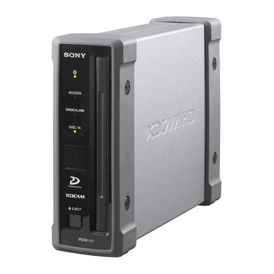
Names and Functions of Parts 2-1 Front Panel ACCESS ERROR/ALARM FILE ACCESS MODE DISC IN EJECT a FILE ACCESS MODE indicator Lights when a file access mode connection (FAM connection) is established. 2-1 Front Panel During an AV/C (Audio/Video Control) connection, it is off. -
Page 27: Eject Button
When the switch is moved to the 1 position, the indicator goes off. When operating the PDW-D1 from an AC power supply, normally leave the AC power switch in the ~ position, and switch the PDW-D1 between the operating and standby states using the ~/1 (on/standby) switch. -
Page 28: Rear Panel
S400 (i.LINK) connector are not output, disconnect the i.LINK cable and connect it again, pushing it straight in. • When connecting the PDW-D1 to a computer with a 6-pin i.LINK connector, connect to the 6-pin i.LINK connector of the computer first. -
Page 29: Chapter 3 Preparations
(see Chapter 5, “Using the Utility Software” (page 46)). To install the utility software, insert the supplied CD-ROM (PDW-D1 PC Utility) in the computer’s CD-ROM drive, and copy all of the following files from the PC_Utility folder of the CD-ROM to an appropriate folder on the computer: •... -
Page 30: Connections And Settings
3-2 Connections and Settings 3-2-1 Connecting to a Nonlinear Editing System (AV/C connection) By connecting this unit to a nonlinear editing system with an AV/C (Audio/Video Control) connection, you can transfer video and audio signals (AV/C data). The following figure shows an example connection. Notes •... -
Page 31: Connecting To A Computer (Fam Connection)
The following figure shows an example connection. Notes • The FAM driver (see page 29) must be installed in advance. • Connect only one PDW-D1 unit to a single computer. 1: i.LINK cable (not supplied) To i.LINK(IEEE1394) connector S400 (i.LINK) - Page 32 3-2 Connections and Settings 1: i.LINK cable (not supplied) To i.LINK(IEEE1394) connector S400 (i.LINK) In the PC operation settings dialog box of the utility software, in the FAM operation section, set “Login” to “Permit” (see page 48). DC IN S400 -AC IN PDW-D1...
-
Page 33: Power Preparations
3-3 Power Preparations This unit can be powered by a battery pack or AC power. 3-3-1 Using AC Power Connect a power cord (not supplied, see page 58) to the AC power inlet connector (page 28) on the rear panel of the unit. 3-3-2 Using a Battery Pack Usable battery packs... -
Page 34: Setting The Date And Time
Replace the hexagonal wrench on the battery adaptor. Align the slots on the back of the battery pack with the projections on the battery adaptor, and pull the battery pack downward. To remove the battery pack Keep the lever on the battery adaptor depressed and slide the battery pack up, and remove. -
Page 35: Handling Discs
3-5 Handling Discs 3-5-1 Discs Used for Recording and Playback This unit uses the following disc for recording and playback: PFD23 Professional Disc (capacity 23.3 Note It is not possible to use the following discs for recording or playback: • Blu-ray Disc •... -
Page 36: Loading And Unloading A Disc
3-5-4 Loading and Unloading a Disc When the ~/1 (on/standby) indicator is lit green, you can load and unload a disc as shown in the following figure. ~/1 (on/standby) switch and indicator To load With the label surface on the right, insert the disc. -
Page 37: Handling Of Discs When Recording Does Not End Normal
resume when the unit is powered on again. Replace the rubber cap, and close the cover. 3-5-7 Handling of Discs When Recording Does Not End Normally (Salvage Function) Recording processing does not end normally if, for example, the unit is powered off during recording, or if battery pack power is exhausted during recording. -
Page 38: Preparations For Recording And Playback
3-6 Preparations for Recording and Playback 3-6-1 Preparations for Recording See 3-2-1 “Connecting to a Nonlinear Editing System (AV/C connection)” (page 30) for information about connections. Switch settings Before beginning recording, make the following switch settings. ~/1 (on/standby) switch (page 27): ~ position Settings In the PC operation settings dialog box of... -
Page 39: Inserting A Disc
Switch settings Before beginning playback, make the following switch settings. ~/1 (on/standby) switch (page 27): ~ position Settings In the PC operation settings dialog box of the utility software (see page 48), set the following items. Login: “Inhibit” (Disables FAM connection.) In the setup menu of the utility software (see page 50), set the following items as... -
Page 40: Chapter 4 Handling Files
Handling Files 4-1 Overview When a computer is connected to this unit in file access mode (FAM connection), you can handle video and audio data as files. The recording conditions during an AV/C connection are fixed at DVCAM format, four audio channels (16-bit), but with an FAM connection, you can write files in DVCAM/MPEG IMX 50/40/30 format, with eight audio channels (16-bit) or four... -
Page 41: File Operation Restrictions
4-1-2 File Operation Restrictions This section explains which operations are possible on files stored in each directory. Root directory File name Content INDEX.XML Contains information about all material on the disc. DISCMETA. Contains the disc ID and disc label. Other files Files other than the above a) Only files which can be overwritten by XDCAM... - Page 42 d) When a C*.MXF file is created, a C*M01.XML file with the same number is generated automatically. e) When a C*.MXF file is deleted, the C*M01.XML file with the same number is also deleted automatically. Edit directory File name Content E*E01.SMI Clip list file *: 0001 to 0099...
- Page 43 b) When a C*.MXF file is deleted, the C*S01.MXF file with the same number is also deleted automatically. General directory File name Content Any file a) File name up to 63 characters b) Only when the write-protect tab on the disc is set to enable recording The following directory operations are possible in the General directory.
-
Page 44: Preparations For File Access
4-2 Preparations for File Access See 3-2-2 “Connecting to a Computer (FAM connection)” (page 31) for information about connections. Switch settings Before beginning file operations, make the following switch settings. ~/1 (on/standby) switch (page 27): ~ position Settings In the PC operation settings dialog box of the utility software (see page 48), set the following items. - Page 45 enables you to browse the proxy AV data, add or modify metadata (titles, comments, essence marks, etc.), or create a clip list. The modified metadata and the created clip list can then be written back to the disc loaded in this unit. Switching from file operations to recording/playback operations In the PC operation settings dialog box of...
-
Page 46: Chapter 5 Using The Utility Software
Using the Utility Software The utility software allows you to carry out the following functions on this unit. • Displaying device information • Changing settings • Disc operations For details of installation of the utility software, see page 29. Notes •... -
Page 47: Names And Functions Of Parts
5-2 Names and Functions of Parts a Menu bar This shows the menus of the utility software. Click a menu name to display the commands for executing functions. • Settings menu PC operation settings: Opens a dialog box to select the language for screen indications and operations, and to enable or disable the FAM connection (see page 48). - Page 48 • Device information menu Basic information: Shows product information and system information (see page 49). Hours Meter: Shows the cumulative number of operating hours of this unit (see page 49). Version: Shows the firmware version information (see page 50). Alarm log: Shows the alarms generated by this unit (see page 50).
-
Page 49: Details Of Functions
Hours Meter Information about the operational history of the unit can be displayed. Use the information as a guide in scheduling periodic maintenance. For periodic maintenance, consult your Sony dealer. Item name Display contents Operation The total number of Hours... -
Page 50: Setup Menu
Item name Display contents Operation Same as Operation Hours (r) Hours (resettable Laser The cumulative light Parameter (r) output time for the optical head (resettable Seek The cumulative seek Running operation time for the Hours (r) optical head (unit: hours, resettable Spindle The cumulative spindle... - Page 51 TIME CODE Item name Settings TC MODE Select the time code recording mode. INT-REGEN: Record the output of the internal time code generator, initialized to time code following continuously upon the time code of the last frame of the last clip on the disc. EXT-REGEN: Record the output of the internal time code...
- Page 52 AUDIO CONTROL Item name Settings IMX DATA When “IMX50,” LENGTH “IMX40,” or “IMX30” is selected in setup menu item “RECORDING FORMAT,” select the audio quantization bit count and number of recording channels. 16bit × 8ch: 16 bits × 8 channels 24bit ×...
- Page 53 • Windows 2000: The Unplug or Eject Hardware dialog appears. • Windows XP: The Safely Remove Hardware dialog appears. Select “Sony XDCAM PDW-D1 IEEE 1394 SBP2 Device” and click Stop. The Stop a Hardware device dialog appears. Select “Sony XDCAM PDW-D1 IEEE 1394 SBP2 Device”...
- Page 54 Owner information setting operations To enter owner information: Using the keyboard, enter alphanumeric characters in the edit box for each item. If an entry is less than four bytes, the remainder is filled with space characters (20h). To enter the country code by selecting from a list: On the right of the edit box, click the ...
-
Page 55: Disc Operation Menu
Item name Settings Date Set the four-digit year (2000 to 2099), month, and day. Time Set the hours, minutes, and seconds. Time zone Select the timezone offset from UTC. Setting the date and time To change the date and time: In the edit boxes, click the value you want to change (year, month, day, hour, minute, second), then adjust the value... - Page 56 A confirmation dialog box appears. In the dialog box, click the Delete button. 5-3 Details of Functions...
-
Page 57: Appendix
Appendix Specifications General Power requirements 100 V to 240 V AC, 50/60 Hz DC (with battery) Power consumption 22 W Peak inrush current (1) Power ON, current probe method: 58 A (240 V), 16 A (100 V) (2) Hot switching inrush current, measured in accordance with European standard EN55103-1: 13 A (230 V) -
Page 58: Related Products
file access mode MPEG IMX: 16 bits/48 kHz (8 channels) or 24 bits/48 kHz (4 channels) DVCAM: 16 bits/48 kHz (4 channels) Proxy audio A-law (8/4 channels, 8 bits, 8 kHz) 1) The MPEG-4 Codec is a product of Ingenient Technologies, Inc. - Page 59 The material contained in this manual consists of information that is the property of Sony Corporation and is intended solely for use by the purchasers of the equipment described in this manual. Sony Corporation expressly prohibits the duplication of any portion of this manual or...
-
Page 60: Sony Corporation
Sony Corporation B&P Company PDW-D1 (SYL) 3-868-752-01 (1) ©2005...