Table of Contents
Advertisement
Quick Links
Advertisement
Table of Contents

Related Manuals for Sony CRX100E


Summary of Contents for Sony CRX100E
- Page 1 3-865-162-11(3) CRX100E CD-R/RW Drive Unit User’s Guide...
-
Page 2: Safety Regulations
To avoid electrical shock, do not open the cabinet. Refer servicing to qualified personnel only. CAUTION As the laser beam in this CRX100E is harmful to the eyes, do not attempt to disassemble the cabinet. Refer servicing to qualified personnel only. The use of optical instruments with this product will increase eye hazard. - Page 3 This unit uses CD-R discs with the following mark. This unit uses CD-ROM discs with the following mark. When you use this unit as a CD player, use compact discs with the following mark. WARNING — For the customers in U.S.A.
- Page 4 Model No.: CRX100E Responsible Party: Sony Electronics Inc. Address: 1 Sony Drive, Park Ridge, NJ. 07656 USA Telephone No.: 201-930-6970 This device complies with Part 15 of the FCC Rules. Operation is subject to the following two conditions: (1) This device may not cause harmful interference, and (2) This device must accept any interference received, including interference that may cause undesired operation.
-
Page 5: Table Of Contents
Contents Introduction Location and Function of Parts and Controls Front Panel ... 7 Rear Panel ... 8 Precautions Example of System Setup Installing the Drive in Your Computer Preparation ... 10 Setting the Jumpers ... 11 Opening the Computer ... 12 Mounting the Drive ... -
Page 6: Introduction
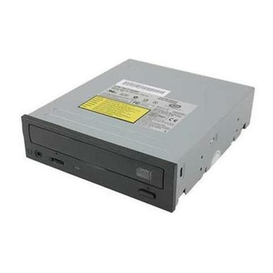
Introduction F e a t u r e s The CRX100E is an internal CD-R/RW (Compact Disc Recordable/ ReWritable) drive unit designed for use with an IBM PC, HP Vectra, or compatible computer. It can write as much as 650 Mbytes of digital data into CD-R disc, and can read as much as 650 Mbytes of digital data stored in a CD- ROM (Compact Disc Read-Only Memory), CD-R and CD-RW disc. -
Page 7: Location And Function Of Parts And Controls
Location and Function of Parts and Controls Front Panel 1 Disc tray Accepts a CD-ROM, CD-R and CD-RW disc on its tray. 2 Emergency eject hole Insert a fine rod into this hole to eject the tray manually in emergencies. 3 Eject button Opens and closes the disc tray. -
Page 8: Rear Panel
Rear Panel 1 F.GND (Frame ground) tab Connect with one of the host computer’s ground cables when the drive’s frame is not in direct contact with the computer. 2 Unused 3 ANALOG AUDIO connector Outputs analog audio signals. 4 Configuration Jumpers See page 11 for details. -
Page 9: Precautions
Precautions Installation • Avoid placing the drive in a location subject to: – high humidity – high temperature – excessive dust – mechanical vibration – direct sunlight. We recommend to use the drive in a horizontal or vertical position. Do not use it in a tilted position. Operation •... -
Page 10: Example Of System Setup
This section provides an example of instruction for installing the CD-R/RW drive unit into your personal computer using the IDE Host Adaptor (ATA-Compliant). To connect the CRX100E directly to the PC’s IDE port, consult your PC manufacturer for instruction. Preparation... -
Page 11: Setting The Jumpers
IDE Card, set the Hard Disk Drive as MASTER and the CRX100E as SLAVE. • If the CRX100E is the only device connected to the IDE Card, set the CRX100E as MASTER. However, it should be noted that some personal computers may use CSEL in lieu of the foresaid MASTER/SLAVE selection. -
Page 12: Opening The Computer
Opening the Computer If your computer has its rear side covered by a plastic panel attached with plastic hook pad, pull it off. Remove the cover mounting screws. Remove the cover of the computer. Mounting the Drive If mounting rails are necessary, attach them to the drive in the same way as your floppy disk drive and slide the drive into the lower drive bay. -
Page 13: Connecting The Drive
Connecting the Drive Connect the drive to the computer with the following connectors: • DC INPUT connector • AUDIO OUT connector (if you plan to connect audio equipment) • INTERFACE CONNECTOR. DC INPUT connector The pin assignment is as follows. After matching the beveled edges, insert the plug of the power supply cable to the DC INPUT connector and push it firmly in place. - Page 14 Frame ground When normally installed, the drive unit is not in contact with the host computer directly and should be grounded. Connect the frame ground tab to one of the host computer’s ground cables. Frame ground tab Frame ground cable The frame ground cable recommended has a AMP 1-480435-0 housing and 170203-2 or 60711-1 contacts.
- Page 15 AUDIO OUT connector The pin assignment is as follows: INTERFACE CONNECTOR Firmly insert one end of the interface cable into the INTER- FACE CONNECTOR. Attach the other end of the cable to the host adapter. Host adapter INTERFACE CONNECTOR INTERFACE cable Installing the Drive Unit into the Computer Audio Signal R signal...
-
Page 16: Mounting The Host Adapter
Mounting the Host Adapter Install the host adapter in one of the available system expansion slots of your computer. Refer to the operating instructions included with the host adapter for complete instructions on installation and settings. Closing the Computer Replace the cover on the computer, being careful to reinstall all Replace the AC power cord and turn on your computer. -
Page 17: Installing The Software Driver
Installing the Software Driver MSCDEX and the device driver for an ordinary CD-ROM drive can be used when using the CRX100E as a CD-ROM drive. Use the device driver for a CD-R/RW drive when using the CRX100E as a recordable or rewritable drive. -
Page 18: Operating The Drive
Operating the Drive This section describes how to start the drive and eject a disc. Starting the Drive Turn on the power of your computer. Press the eject button. The tray comes out automatically. Place a disc in the tray with its label side up. Operating the Drive... - Page 19 Note: When the drive is set up in vertical position, use the disc locks to prevent your disc from falling. See “How to Use the Disc Locks” on page 21 for details. Disc locks Gently push the tray or press the eject button to close the tray. The drive may begin reading the Table of Contents (TOC) data when it accepts the disc.
-
Page 20: Ejecting The Disc
Ejecting the Disc To eject the disc, press the eject button on the front panel. The tray comes out automatically. Note: The eject button does not work if it is disabled by the software you are using. Opening the tray manually in an emergency You can open the tray manually when it fails to come out by means of the eject button or software commands. -
Page 21: How To Use The Disc Locks
How to Use the Disc Locks The disc tray has four disc locks that prevent the disc from falling when the drive is set up in vertical position. Disc locks Note: When the drive is used in horizontal position, you do not need to lock the disc. - Page 22 When the drive’s right side is down To facilitate disc handling, set the disc locks B, C and D into the locked position, and leave the disc lock A in the unlocked position. When the drive’s left side is down To facilitate disc handling, set the disc locks A, C and D into the locked position, and leave the disc lock B in the unlocked position.
-
Page 23: Specifications
Specifications General Host interface Read Function Acceptable discs: Write Function Applied Format: Writing Method: Cache memory(R/W) Disc diameter: Rotational speed Innermost track: ATAPI compliant CD-ROM mode-1 data discs CD-ROM XA discs CD-Audio discs Audio-combined CD-ROM discs CD-I discs CD-I Ready Discs Photo CD (Single and Multi session)discs Video CD discs CD-EXTRA discs... - Page 24 Outermost track: Drive performance Data transfer rate Sustained rate: Burst rate: Access time Random stroke: Reliability Read error rate (includes retry, normal disc) L-EC on: L-EC off: Audio Output level Line out: Head phone: Environmental conditions Temperature and humidity Operating Transportation Storage Temperature and...
- Page 25 Vibration Operating Non-operating Transportation Shock Operating Non-operating Transportation Dimensions and weight Dimensions Mass Power requirement Voltage Ripple Current Hold track state Seeking Spin up/Write Sleep Read: 1.96 m /s (0.2 G o-p) at 5 Hz to 300 Hz (sweep) Write: 0.98 m /s (0.1G o-p) at 5Hz to 300 Hz(sweep) 19.6 m /s...
- Page 26 Connectors Power-in/Interface/ID Jumper Switch/Audio connector Recommended Mating (Female) Connectors for POWER connector (Pin Header: AMP 170147-1 or 4 AWG24-18 / AMP 170120-1 or 4 AWG20-14) for INTERFACE connector and 2 pin out connector for AUDIO connector (4pin) for GROUND TAB L a s e r Type Wave length...
- Page 27 Diese Ausrüstung erfüllt die Europäischen EMC-Bestimmungen für die Verwendung in folgender / folgenden Umgebung(en): • Wohngegenden • Gewerbegebiete • Leichtindustriegebiete (Diese Ausrüstung erfüllt die Bestimmungen der Norm EN55022, Klasse B.) Dimension diagram +0.05 -0.45 Important: Screws must not extend more than 6.0mm into the side panels or the bottom plate.
- Page 28 CRX100E CD-R/RW Drive Unit User’s Guide ©1998 by Sony Corporation Printed in Japan...