Sony EVI-D70 Technical Manual
Color video camera
Hide thumbs
Also See for EVI-D70:
- Technical manual (60 pages) ,
- Brochure & specs (4 pages) ,
- Operating instructions manual (56 pages)

Related Manuals for Sony EVI-D70


Summary of Contents for Sony EVI-D70
- Page 1 A-BS4-100-11 (1) Color Video Camera Technical Manual EVI-D70/D70P 2003 Sony Corporation...
-
Page 2: Table Of Contents
Initial Settings, Position Preset ... 25 Mode Condition ... 27 Command List ... 31 VISCA RS-232C/RS-422 Commands ... 31 EVI-D70/P Commands ... 39 D30/D31 Mode ... 52 Overview ... 52 Switching the Mode ... 52 Accepting or Sending Back Commands ... 53 Translating Parameters ... -
Page 3: Features
• An EXview HAD CCD provides 380,000 (EVI-D70)/ 410,000 (EVI-D70P) effective picture elements (pixels) enabling high-resolution imaging with this camera. • The use of VISCA commands allows you to control the camera from a computer. • High-speed, wide angle PAN and TILT functions and... -
Page 4: Connection
S VIDEO VISCA cable (not supplied) to VISCA RS-232C IN to RS-232C To VISCA IN of to VISCA other EVI-D70/ RS-232C OUT D70Ps (when connecting to more than one camera) to VISCA RS-422 AC power adaptor MPA-AC1 (supplied) Power cord (supplied) •... -
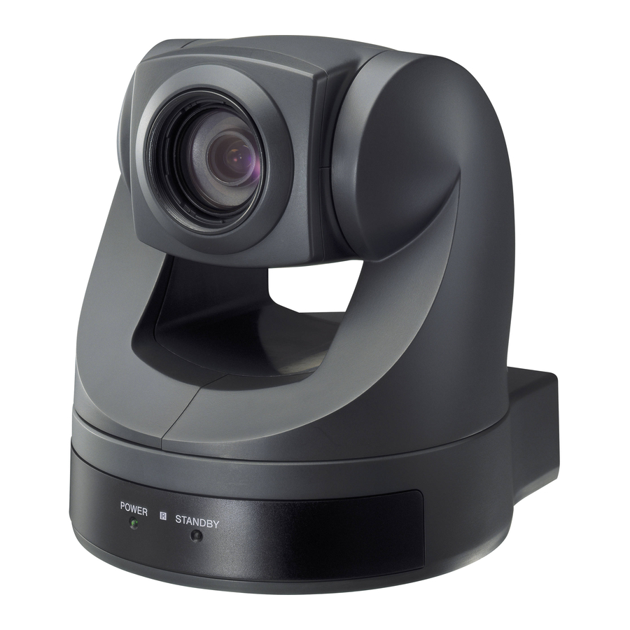
Page 5: Locations Of Controls
Locations of Controls Main Unit Front Rear 5 6 7 9 q; qa qs qd 1 Lens A wide conversion lens can be attached. 2 Sensor for the Remote Commander 3 POWER lamp 4 STANDBY lamp 5 Sensor for the Remote Commander 6 IMAGE FLIP switch Flips the image upside down and executes Pan/Tilt movement according to the camera installation. -
Page 6: Remote Commander
7 IR SELECT switch 8 VISCA RS-422 connector A VISCA RS-422 connector plug is attached to the unit at the factory. 9 VIDEO (output) connector 0 S VIDEO (output) connector qa VISCA RS-232C IN connector qs VISCA RS-232C OUT connector qd DC IN 12V connector qf Tripod screw hole qg BOTTOM switch... -
Page 7: Basic Functions
Zoom The camera employs an 18 optical zoom lens combined with a digital zoom function allowing you to zoom up to 216 . Lens specifications: Optical 18 , f = 4.1 to 73.8 mm (F1.4 to F3.0) The horizontal angle of view is approximately 48 degrees (wide end) to 2.7 degrees (tele end). -
Page 8: White Balance
To avoid AF error from continuous 24 hour AF mode usage, daily initialization of lens system using the CAM_Initialize command is recommended. The CAM_Initialize command takes less than 3 seconds to initialize the focus and zoom. • Manual Focus Mode MF (Manual Focus) has both a Standard Speed Mode and a Variable Speed Mode. - Page 9 AE – Shutter Priority The shutter speed can be set freely by the user to a total of 22 steps – 16 high speeds and 6 low speeds. When the slow shutter is set, the speed can be , or s.
-
Page 10: Exposure Compensation
When switching from the Shutter Priority mode to the Bright mode, the shutter speed set in the Shutter Priority mode is maintained. Spot Exposure Mode In Full Auto AE, the level for the entire screen is computed and the optimum Auto Iris and Gain levels are determined. - Page 11 Auto ICR Mode Auto ICR Mode automatically switches the settings needed for attaching or removing the IR Cut Filter. With a set level of darkness, the IR Cut Filter is automatically disabled (ICR ON), and the infrared sensitivity is increased. With a set level of brightness, the IR Cut Filter is automatically enabled (ICR OFF).
- Page 12 Mute Blanks the screen and sends out a synchronizing signal. Lens Initialization Initializes the zoom and focus of the lens. Even when power is already on, it initializes the zoom and the focus. AutoPowerOff If an operation is not attempted via either a VISCA command or the remote controller during a pre-set time period (from 1 to 65,535 minutes), the power will automatically turn off (Standby).
-
Page 13: Title Display
Title Display The camera can be given a title containing up to 20 characters such as “ENTRANCE” or “LOBBY”. The position of the first character (horizontal, vertical) of the title, blinking state, and color can also be changed. Vposition Hposition 00: Does not blink Blink 01: Blinks... - Page 14 ALARM Setting Command List Command Set Command CAM_Alarm Set Mode Set Day Night Level VISCA Mode Code (pp) Details of Mode Set the internal focus position. When focus movement is detected, the detect signal is High. When focus goes back to the previous position, the detect signal is Low. Set a fixed period of time.
- Page 15 Flowchart of 12 Modes Function Mode “00” Set the Focus Position Hysteresis. Focus moves outside of the hysteresis. High level signal output Focus goes back to the previous position. Low level signal output Set to the factory preset Alarm On Focus Position into memory AE moves Focus...
- Page 16 Mode “01” * Repeat this loop until Alarm off. Update the Focus position data. Alarm On AE moves. Focus moves outside of the hysteresis. High level signal output AE does not move for a period of time. Low level signal output Basic Functions Focus Position into memory Hysteresis is set to the factory...
- Page 17 Mode “02” Set the AE level Hysteresis. AE moves outside of the hysteresis. High level signal output AE goes back to the previous level. Low level signal output Set to the factory preset Alarm On AE Level into memory AE moves. Bright AE Level High...
- Page 18 Mode “03” * Repeat this loop until Alarm off. Alarm On AE moves. AE moves outside of the hysteresis. High level signal output AE does not move for a period of time. Low level signal output Update the AE level data Basic Functions AE level into memory Hysteresis is set to the factory...
- Page 19 Details of Mode “01” to “03” Alarm ON Hysteresis Focus Pos/ AE Level Signal level T1: Reset interval timer (5sec) T2: Detect timer (2sec) T3: High level signal count timer (2sec) Reset Reset Reset High Basic Functions Reset...
- Page 20 Mode “04” High output result of mode “00” High output result of mode “02” Mode “05” High output result of mode “00” High output result of mode “03” The same flow for the low level signal High output The same flow for the low level signal High output Basic Functions...
- Page 21 Mode “06” High output result of mode “00” High output result of mode “02” Mode “07” High output result of mode “00” High output result of mode “03” The same flow for the low level signal High output The same flow for the low level signal High output Basic Functions...
- Page 22 Mode “08” High output result of mode “00” High output result of mode “02” High output Mode “09” High output result of mode “00” High output result of mode “03” High output The same flow for low level signal High output result of mode “02” High output High output The same flow for low level signal...
- Page 23 Mode “0A” High output result of mode “00” High output result of mode “02” High output Mode “0B” High output result of mode “00” High output result of mode “03” High output The same flow for low level signal High output result of mode “02” High output High output The same flow for low level signal...
- Page 24 Day-Night Mode (Mode “0C”) Set the Day-Night Mode and the Day/ Night AE level. Alarm On AE moves. Brightness is higher than Day AE level. High level signal output Low level signal output Bright AE level Night AE level Dark Signal level Setting by the VISCA Cmd.
-
Page 25: Initial Settings, Position Preset
Initial Settings, Position Preset The initial values are those set at the factory. Settings for items in Position presets 1 to 6 that will be retained even when the power to the camera is turned off are indicated by a “O,” those that will be lost are indicated by an “X.”... - Page 26 Mode/Position Title Setting Alarm On/Off Alarm Mode Alarm Detect Level Notes • The number of times data can be written to the EEPROM (by executing Position Preset) is limited. • If you want the camera status and Pan/Tilt positions in effect before the camera is turned off to be retained when the power is turned OFF, then turned ON again, have the camera memorize those positions in POSITION 1.
-
Page 27: Mode Condition
Basic Functions... - Page 28 Basic Functions...
- Page 29 Basic Functions...
- Page 30 Basic Functions...
-
Page 31: Command List
The devices on the network are assigned addresses. 1) VISCA is a protocol which controls consumer camcorders developed by Sony. “VISCA” is a trademark of Sony Corporation. Command List The address of the controller is fixed at 0. The addresses of the peripheral devices are 1, 2, 3 ... -
Page 32: Visca Communication Specifications
EVI-D70/P assigned address 2 is 82H. In the command list, as the header is 8X, input the address of the EVI-D70/P at X. The header of the reply packet from the EVI-D70/P assigned address 1 is 90H. - Page 33 No socket (to be cancelled) X0 6Y 41 FF Command not executable X = 9 to F: EVI-D70/P address + 8, Y = socket number Socket number When command messages are sent to the EVI-D70/P, it is normal to send the next command message after waiting for the completion message or error message to return.
-
Page 34: Visca Device Setting Command
8X 01 00 01FF IF_Clear (broadcast) 88 01 00 01 FF X = 1 to 7: EVI-D70/P address (For inquiry packet) X = 9 to F: EVI-D70/P address +8 (For reply packet) VISCA interface and inquiry CAM_VersionInq Returns information on the VISCA interface. - Page 35 IR Commander Signal (OUTPUT) N.C. No Connection IR OUT outputs the signals of the Remote Commander at 0 to 5 V when the IR OUT switch is set to ON. • EVI-D70/P Windows D-sub 9 pin 1. DTR 1. CD 2. DSR 2.
-
Page 36: Connector Pin Assignments
Using the VISCA RS-422 connector pin assignments The VISCA RS-422 connector pin assignments 1 2 3 4 5 6 7 8 9 VISCA RS-422 Pin No. Function TXD IN+ TXD IN– RXD IN+ RXD IN– TXD OUT+ TXD OUT– RXD OUT+ RXD OUT–... - Page 37 VISCA Command/ACK Protocol Command Command Message General Command 81 01 04 38 02 FF (Example) 81 01 04 38 FF (Example) 81 01 04 38 02 FF (Example) 81 01 04 08 02 FF (Example) Inquiry Command 81 09 04 38 FF (Example) 81 09 05 38 FF (Example)
-
Page 38: Error Messages
VISCA Camera-Issued Messages ACK/Completion Messages Command Messages z0 4y FF (y:Socket No.) Completion z0 5y FF (y:Socket No.) z = Device address + 8 Error Messages Command Messages Syntax Error z0 60 02 FF Command Buffer Full z0 60 03 FF Command Canceled z0 6y 04 FF (y:Socket No.) -
Page 39: Evi-D70/P Commands
EVI-D70/P Commands EVI-D70/P Command List (1/4) Command Set Command AddressSet Broadcast IF_Clear Broadcast CommandCancel CAM_Power CAM_AutoPowerOff Direct CAM_NightPoweroff Direct CAM_Zoom Stop Tele(Standard) Wide(Standard) Tele(Variable) Wide(Variable) Direct CAM_DZoom Combine Mode Separate Mode Stop Tele(Variable) Wide(Variable) x1/Max Direct CAM_Focus Stop Far(Standard) Near(Standard) - Page 40 EVI-D70/P Command List (2/4) Command Set Command AF Sensitivity Normal CAM_AFMode Normal AF Interval AF Zoom Trigger AF Active/Interval Time CAM_ZoomFocus Direct CAM_Initialize Lens Comp Scan CAM_WB Auto Indoor Outdoor One Push WB Manual One Push Trigger CAM_RGain Reset Down...
- Page 41 EVI-D70/P Command List (3/4) Command Set Command CAM_ExpComp Reset Down Direct CAM_Backlight CAM_SpotAE Position CAM_Aperture Reset Down Direct CAM_LR_Reverse CAM_Freeze CAM_PictureEffect Neg.Art B&W CAM_ICR CAM_AutoICR CAM_Memory Reset Recall CAM_Display On/Off CAM_Title Title Set1 Title Set2 Title Set3 Title Clear CAM_Mute...
- Page 42 EVI-D70/P Command List (4/4) Command Set Command CAM_KeyLock CAM_IDWrite CAM_Alarm SetMode SetDayNightLevel Alarm (Reply) IR_Receive On/Off IR_ReceiveReturn Pan-tiltDrive Down Left Right UpLeft UpRight DownLeft DownRight Stop AbsolutePosition RelativePosition Home Reset Pan-tiltLimitSet LimitSet LimitClear Command Packet Comments 8x 01 04 17 00 FF...
- Page 43 EVI-D70/P Inquiry Command List (1/2) Inquiry Command Command Packet CAM_PowerInq 8x 09 04 00 FF CAM_AutoPowerOffInq 8x 09 04 40 FF CAM_NightPowerOff Inq 8x 09 04 41 FF CAM_ZoomPosInq 8x 09 04 47 FF CAM_DZoomModeInq 8x 09 04 06 FF...
- Page 44 EVI-D70/P Inquiry Command List (2/2) Inquiry Command Command Packet CAM_LR_ReverseModeInq 8x 09 04 61 FF CAM_FreezeModeInq 8x 09 04 62 FF CAM_PictureEffectModeInq 8x 09 04 63 FF CAM_ICRModeInq 8x 09 04 01 FF CAM_AutoICRModeInq 8x 09 04 51 FF CAM_MemoryInq...
- Page 45 EVI-D70/P Block Inquiry Command List Lens control system inquiry commands ... Command Packet 8x 09 7E 7E 00 FF Byte Bit Comments Destination Address Source Address 0 Completion Message (50h) Zoom Position (HH) Zoom Position (HL) Zoom Position (LH) Zoom Position (LL)
- Page 46 Camera control system inquiry commands .. Command Packet 8x 09 7E 7E 01 FF Byte Bit Comments Destination Address Source Address 0 Completion Message (50h) R Gain (H) R Gain (L) B Gain (H) B Gain (L) Byte Bit Comments WB Mode Aperture Gain Exposure Mode...
- Page 47 Other inquiry commands ... Command Packet 8x 09 7E 7E 02 FF Byte Bit Comments Destination Address Source Address 0 Completion Message (50h) Auto ICR 1: On 0: Off Power 1: On 0: Off ICR 1: On 0: Off Freeze 1:On 0:Off LR Reverse 1:On 0:Off Mute 1: On 0: Off Title Display 1: On 0: Off...
- Page 48 Enlargement Function Query Command ... Command Packet 8x 09 7E 7E 03 FF Byte Bit Comments Destination Address Source Address 0 Completion Message (50h) Digital Zoom Position (H) Digital Zoom Position (L) AF Activation Time (H) AF Activation Time (L) Byte Bit Comments AF Interval Time (H)
-
Page 49: Visca Command Setting Values
VISCA Command Setting Values Exposure Control (1/2) NTSC Shutter Speed 10000 6000 4000 3000 2000 1500 1000 Iris F1.4 F1.6 F2.0 F2.4 F2.8 F3.4 F4.0 F4.8 F5.6 F6.8 F8.0 F9.6 CLOSE Gain 10000 6000 3500 2500 1750 1250 1000 Command List 28 dB 26 dB 24 dB... - Page 50 Exposure Control (2/2) IRIS Bright F1.4 F1.4 F1.4 F1.4 F1.4 F1.4 F1.4 F1.4 F1.4 F1.4 F1.4 F1.4 F1.4 F1.4 F1.4 F1.6 F2.0 F2.4 F2.8 F3.4 F4.0 F4.8 F5.6 F6.8 F8.0 F9.6 CLOSE Exposure Comp. –1 –2 –3 –4 –5 –6 –7 Zoom Ratio and Zoom Position (for reference)
-
Page 51: Title Setting
When using Digital Zoom Separate Mode (CAM_DZoomPos Inq) Magnification Position Data Lens Control 0000 4000 Zoom Position Wide end Optical Tele end 1000 C000 Focus Position Far end Near end 1000: Over Inf 2000: 8.0 m 3000: 3.5 m 4000: 2.0 m As the distance on the left 5000: 1.4 m will differ due to... -
Page 52: D30/D31 Mode
D70/P using VISCA commands for the EVI-D30/D31. Most of the VISCA commands for the EVI-D70/P correspond to one for the EVI-D30/D31. However, some of the VISCA commands for the EVI-D70/P are different from those for the EVI-D30/D31 in definitions of parameters. -
Page 53: Accepting Or Sending Back Commands
Accepting or Sending Back Commands When accepting commands Type of command Common to both the D30/D31 and Common parameters D70/P Different parameters CAM_Memory Reset Only for the D70/P Only for the D30/D31 When accepting inquiry commands Type of command Common to both the D30/D31 and Common parameters D70/P Different parameters Only for the D70/P... -
Page 54: Translating Parameters
Translation 0000h to 03FFh Translates within a rage of 08D0h to 5700h The EVI-D70/P translates the parameters to let the camera obtain the same zoom position that is defined by the D30/D31’s parameter. (The values given below are calculated values.) -
Page 55: Shutter Speed
(1/10000) 0015h Translation when answering inquiry commands The EVI-D70/P translates its parameters to the D30/ D31’s parameters and sends them back. However, during the period from the instant the camera accepts the CAM_Shutter Direct command to the instant the camera accepts another CAM_Shutter or CAM_AE command, it sends back the current D30/D31 parameters. - Page 56 D70/P parameters are converted to D30/D31 parameters and sent back. Iris conversion • Parameter conversion when a command is received D30/D31 parameters are converted to D70/P parameters according to the table below. EVI-D70/P EVI-D30/D31 Gain (dB) Parameters 0000h 0001h 0002h...
- Page 57 Pan/tilt speed The actual speed that is defined by the parameters corresponds to that of the EVI-D30/D31. When the camera receives commands such as Pan- tiltDrive Home, Reset, or CAM_Memory Recall, that do not include speed indications, these operations are carried out at the same speed as they would be when the D30/D31 mode is set to OFF.
- Page 58 When you execute the Relative position command 88 times, one step after another to turn the camera to the right side: Cameras EVI-D30/D31 EVI-D70/P whose D30/D31 mode is ON For Absolute Position commands, the permissible range for drive settings are the same as those for the EVI-D30/D31.
-
Page 59: Specifications
(WIDE end, extreme close-up settings with VISCA control) : 10 mm ( Minimum illumination 1 lx (F1.4)/with 50 IRE Shutter speed EVI-D70: 1/1 to 1/10,000 s (VISCA control) EVI-D70P: 1/1 to 1/10,000 s (VISCA control) Horizontal resolution NTSC : 470 TV (WIDE end) - Page 60 Dimensions Front 132 (5 170° Right side 90° 30° 66 (2 144 (5 Bottom 24.5 ( 170° Specifications 7.4 ( depth 5 ( BOTTOM switch Tripod screw hole 1/4-20 UNC, depth 6.5 ( Unit: mm (inches)
-
Page 61: Precautions
Do not apply excessive voltage. (Use only the specified voltage.) Otherwise, you may get an electric shock or a fire may occur. In case of abnormal operation, contact your authorized Sony dealer or the store where you purchased the product.