Table of Contents
Advertisement
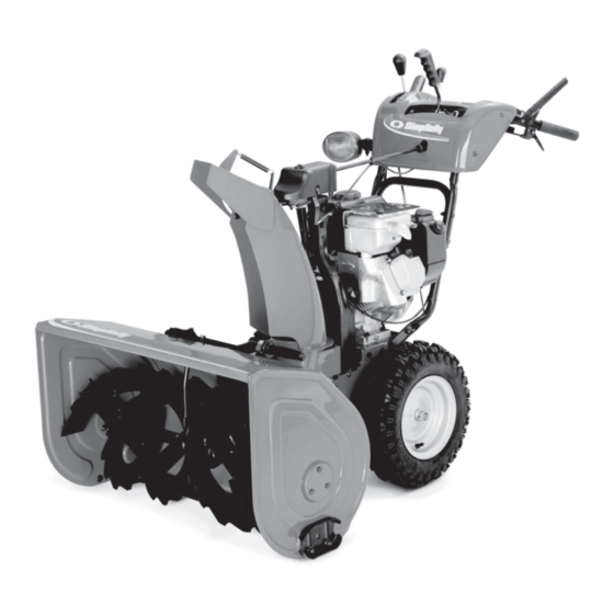
OPERATOR'S
MANUAL
Large Frame
Snowthrowers
8526 Models
Mfg. No.
Description
1694984
L8526E, 8.5HP Snowthrower
1695082
L8526EX, 8.5HP Snowthrower (CE)
1694993
85268E, 8.5HP Snowthrower
1695093
E85268E, 8.5HP Snowthrower (CE)
9528 Models
Mfg. No.
Description
1694985
L9528E, 9.5HP Snowthrower
1695083
L9528EX, 9.5HP Snowthrower (CE)
1694994
95288E, 9.5HP Snowthrower
1695094
E95288E, 9.5HP Snowthrower (CE)
10530 Models
Mfg. No.
Description
1694986
L10530E, 10.5HP Snowthrower
1695084
L10530EX, 10.5HP Snowthrower (CE)
1694995
105308E, 10.5HP Snowthrower
1695095
E105308E, 10.5HP Snowthrower (CE)
11532 Models
Mfg. No.
Description
1694987
L11532E, 11.5HP Snowthrower
1694996
115328E, 11.5HP Snowthrower
1695096
E115328E, 11.5HP Snowthrower (CE)
TP 100-4339-00-LW-SN
1733286
Revision 00
Rev. Date 8/2006
Advertisement
Table of Contents

Related Manuals for Snapper 8526, 9528, 10530, 11532


Summary of Contents for Snapper 8526, 9528, 10530, 11532
- Page 1 OPERATOR’S MANUAL Large Frame Snowthrowers 8526 Models Mfg. No. Description 1694984 L8526E, 8.5HP Snowthrower 1695082 L8526EX, 8.5HP Snowthrower (CE) 1694993 85268E, 8.5HP Snowthrower 1695093 E85268E, 8.5HP Snowthrower (CE) 9528 Models Mfg. No. Description 1694985 L9528E, 9.5HP Snowthrower 1695083 L9528EX, 9.5HP Snowthrower (CE) 1694994 95288E, 9.5HP Snowthrower 1695094...
-
Page 2: Table Of Contents
CONTENTS: Safety Rules & Information General...2 Training ...4 Preparation ...4 Operation...4 Children ...5 Clearing a Clogged Discharge Chute ...5 Service, Maintenance and Storage ...5 Emissions ...3 Decals...6 Safety Icons ...8 Identification Numbers...9 Features, Controls, & Operation Control Locations...10 General Operation Checks Before Each Start-Up ...12 Starting Controls...13 Starting the Engine...14... -
Page 3: Safety Rules & Information
Safety Rules & Information Read the Manual The operator’s manual contains important safety information you need to be aware of BEFORE you operate your unit as well as DURING operation. Safe operating techniques, an explanation of the product’s features and controls, and maintenance information is included to help you get the most out of your equipment investment. -
Page 4: Safety Rules And Information
Moving Parts This equipment has many moving parts that can injure you or someone else. However, if you are standing in the operator’s position, and follow all the rules in this book, the unit is safe to operate. The auger and impeller have spinning parts that can amputate hands and feet. Do not allow anyone near the equipment while it is running! DO NOT clear the discharge chute by hand. -
Page 5: Training
Safety Rules & Information This machine is capable to amputating hands and feet and throwing objects. Read these safety rules and follow them closely. Failure to obey these rules could result in loss of control of unit, severe personal injury or death to you, or bystanders, or damage to property or equipment. -
Page 6: Children
21. Keep in mind the operator is responsible for acci- dents occurring to other people or property. 22. Data indicates that operators, age 60 years and above, are involved in a large percentage of power equipment-related injuries. These operators should evaluate their ability to operate the unit safely enough to protect themselves and others from injury. -
Page 7: Decals
Decals DECALS This unit has been designed and manufactured to pro- vide you with the safety and reliability you would expect from an industry leader in outdoor power equipment. Although reading this manual and safety instructions it contains will provide you with the necessary basic knowl- edge to operate this equipment safely and effectively, we have placed several safety labels on the unit to remind you of this important information while you are operating... - Page 8 Part No. 1732618 Shift Decal Part No. 1733059 - DANGER / WARNING Main Dash Decal, CE, w/o Easy Turn Part No. 1727207 Discharge Chute Danger Decal ALL MODEL DECALS Part No. 1733443 Chute Release CE MODEL DECALS Part No. 1733060 - DANGER / WARNING Main Dash Decal, CE, w/ Easy Turn Part No.
-
Page 9: Safety Icons
Safety Icons SAFETY ICONS WARNING: READ OPERATOR’S MANUAL. Read and understand the Operator’s Manual before using this machine. DANGER: THROWN OBJECTS. This machine is capable of throwing objects and debris. Keep bystanders away. WARNING: REMOVE KEY BEFORE SERVICING. Remove the key, disconnect spark plug wire, and consult technical litera- ture before performing repairs or maintenance. -
Page 10: Identification Numbers
Identification Numbers When contacting your authorized dealer for replace- ment parts, service, or information you MUST have these numbers. Record your model name/number, manufacturer’s identi- fication numbers, and engine serial numbers in the space provided for easy access. These numbers can be found in the locations shown. -
Page 11: Features, Controls, & Operation
Please take a moment and familiarize yourself with the name, location, and function of these controls so that you will better understand the safety and operating instructions provided in this manual. CONTROL LOCATIONS The information below briefly describes the function of individual controls. Starting, stopping, and driving require the combined use of several controls applied in specific sequences. -
Page 12: Auger Control
Auger Control Engages the auger/impeller when depressed. Releasing the control stops the auger/impeller. Chute Direction Control Push the lever forward to unlock the rotator control. Moving the lever to the left will turn the spout to the left side and moving the lever to the right will rotate the spout to the right side. -
Page 13: General Operation
Operation GENERAL OPERATION CHECKS BEFORE EACH START-UP 1. Make sure all safety guards are in place and all nuts, bolts and clips are secure. 2. Check to make sure that the clean-out is attached to the auger housing. Do not operate the machine with- out the clean-out tool properly stored on the auger housing. -
Page 14: Starting Controls
STARTING CONTROLS See Figure 1 for the following instructions. Electric Start A. Electric Start Button - The Electric Start Button (A) activates an electric starter mounted to the engine, eliminating the need to pull the starter han- dle. The Electric Start Button operates on 120 Volts AC, which is provided by connection to the extension cord provided with units equipped with this feature. -
Page 15: Starting The Engine
Operation STARTING THE ENGINE 1. Turn the fuel valve (B, Figure 1, Intek Models) to the ON position. 2. Switch the stop switch (H, Power Built models) to the on position. 3. Insert the engine key (F) into the engine key slot and push fully in to the RUN position. -
Page 16: Ground Speed Selector
GROUND SPEED SELECTOR Use the speed selector (A, Figure 2) to control the drive speed of the snowthrower. There are five forward speeds and two reverse speeds. Use the lower speeds to blow deep or wet snow. Use the higher speeds to blow light snow or to drive the snow- thrower without blowing snow. -
Page 17: Easy-Turn And Traction Drive Lock
Operation FULL TRACTION Both Wheels Drive Figure 5. Easy Turn Control EASY TURN™ FREEWHEELING AND TRACTION DRIVE LOCK While Clearing Snow: For easy turning when using the snowthrower, squeeze the Easy Turn™ lever (Figure 5). Engaging the Easy Turn™ lever releases the left traction wheel but allows the right wheel to continue driving (Figure 5). -
Page 18: After Each Use
AFTER EACH USE Normal use of the snowthrower may result in a build-up of packed snow in and around the starter cord housing and around engine controls. Heat from the engine will usually prevent the snow from freezing solid while the unit is running, but after the engine is shut down, some snow may continue melting from engine heat, and later freeze around some moving parts as the unit cools. -
Page 19: Regular Maintenance
MAINTENANCE SCHEDULE MAINTENANCE REQUIRED Check / Lubricate Free-Hand Linkage. Lubricate snowthrower. Check tire pressure. Change engine oil.* Clean or replace spark plug. Check drive linkage/belt tension. Lubricate Axle Shafts. Check auger gear case lubrication.** Lubricate Auger Shaft.*** * Change original oil after two hours of operation. ** Check oil level each fall and spring. -
Page 20: Lubrication
LUBRICATION IMPORTANT NOTE It is very important that grease fittings on the auger shaft are lubricated regularly. If auger rusts to shaft, damage to worm gear may occur if shear pins do not break. To prevent wheels rusting to axles, it is also necessary to remove the wheels and grease the axles regularly. -
Page 21: Check / Lubricate Free-Hand Linkage
Regular Maintenance CHECK / LUBRICATE FREE-HAND LINKAGE Check the function of the Free-Hand controls: the con- trols should function as described in the CONTROLS section. It is critical for the safe operation of the unit that the controls disengage when released. Lubricate as shown in figure 13. -
Page 23: Troubleshooting, Adjustments, & Service Troubleshooting
TROUBLESHOOTING This section provides troubleshooting and service instructions. Locate the problem and check the possible cause/remedy in the order listed. Also, refer to the engine manufacturer’s Owner’s Manual for additional information. For problems not covered here, contact your local deal- PROBLEM Engine fails to start. - Page 24 PROBLEM Auger rotates, but snow is not thrown far enough Poor traction Auger does not stop when auger lever is released Snowthrower does not stop when drive lever is released Snowthrower does not drive and auger does not rotate. Discharge control is difficult to operate.
-
Page 25: Speed Selector Adjustment
Adjustments AUGER DRIVE ADJUSTMENT WARNING Do not over-tighten, as this may lift the lever and cause auger drive to be engaged without depressing the Auger Control. 1. Check that the auger cable (A, Figure 15) is on top of cable button (B) as show in Figure 15. 2. -
Page 26: Traction Drive Adjustment
Figure 17. Traction Drive Cable Adjustment A. Cable Boot B. Traction Drive Cable C. “Z” Hook D. Cable Adjustment Bracket Note: If the cable is too slack the unit will not drive. If the cable is too tight the drive will be engaged without push- ing the handles down. -
Page 27: Easy Turn Cable Adjustment
Adjustments EASY TURN™ CABLE ADJUSTMENT If the Easy Turn™ cable has stretched, the gears will not disengage when the control lever is activated. Adjust the cable using the following procedure. 1. Turn the engine off and disconnect the spark plug wire. -
Page 28: Shear Pin Replacement
SHEAR PIN REPLACEMENT WARNING Do not go near the discharge chute or auger when the engine is running. Do not run the engine with any cover or guard removed. Under most circumstances, if the auger strikes an object which could cause damage to the unit, the shear pin will break. -
Page 29: Belt Replacement
Service BELT REPLACEMENT Auger Drive Belt The drive belts are of special construction and must be replaced with original factory replacement belts available from your nearest authorized service center. Some steps require the assistance of a second person. If the auger drive belt is damaged, the snow thrower will not discharge snow. - Page 30 Figure 27. Spout Rotator Rod A. Special Nut B. Cover C. Hair Pin D. Spout Rotator Rod 15. Index or point the spout rotator to the center of the machine so the rotator control is in the center of the dash panel.
-
Page 31: Traction Drive Belt
Service Traction Drive Belt If the snow thrower will not move forward, check the trac- tion drive belt for wear or damage. If the traction drive belt is worn or damaged, replace the belt as follows. 1. Disconnect the spark plug wire. 2. -
Page 32: Specifications
NOTE: Specifications are correct at time of printing and are subject to change without notice. The power ratings for an individual engine model are initially developed by starting with SAE (Society of Automotive Engineers) code J1940 (Small Engine Power & Torque Rating Procedure) (Revision 2002–05). Given both the wide array of products on which our engines are placed, and the variety of environmental issues applicable to operating the equipment, it may be that the engine you have purchased will not develop the rated horsepower when used in a piece of power equipment (actual “on–site”... -
Page 33: Replacement Parts & Accessories
REPLACEMENT PARTS Replacement parts are available from your authorized dealer. Always use genuine Simplicity / Snapper Service Parts. MAINTENANCE ITEMS Many convenient and helpful service and maintenance items are available from you authorized dealer. Some of these items include: Engine Oil... - Page 34 500 N Spring Street / PO Box 997 Port Washington, WI 53074-0997 www.SimplicityMfg.com P R O D U C T S 535 Macon Street McDonough, GA 30253 www.Snapper.com © Copyright 2006, Briggs & Stratton. All Rights Reserved. Printed in USA.