
Related Manuals for Smooth Fitness Motorized Treadmill 8.25E


Summary of Contents for Smooth Fitness Motorized Treadmill 8.25E
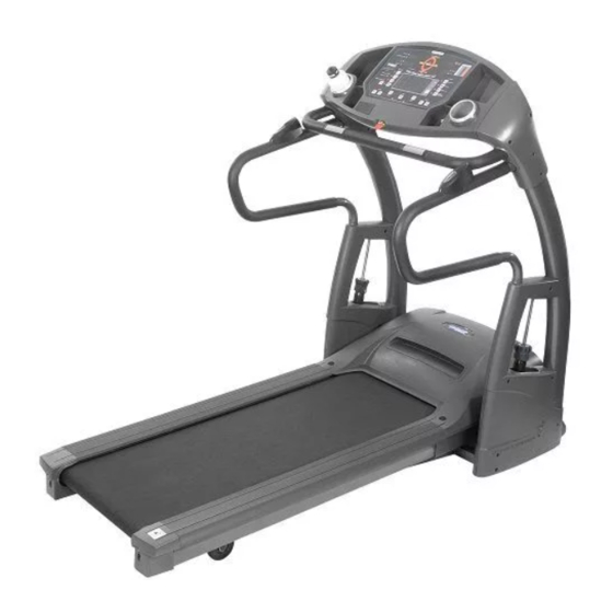
- Page 1 USER’S MANUAL 8.25E MOTORIZED TREADMILL MODEL NUMBER: 8.25E USER WEIGHT LIMITATION: 400 lbs.(180kgs) SERVICENUMBER: 0800-09 72 100 SERIAL NUMBER (found on frame):...
- Page 2 • Place on a level surface, with 6 feet (2 m) of clearance behind it. Do not place the treadmill on any surface that blocks air openings. To protect the floor or carpet from damage, place a mat under the treadmill.
-
Page 3: Power Requirements
This treadmill is provided with two different grounding plugs for Central Europe and United Kingdom. Please choose the right one and plug in your treadmill. Please make sure that your local voltage is appropriate for the power requirements of this treadmill before you plug it in. This product is for use with a voltage of 230V+ 5%. - Page 4 Always care that you mount on the equipment steady before you start to use the equipment. Dismount from the equipment after all parts are stop. Always check the easily wear components like pulley etc. to prevent danger. There is an emergency stop to prevent dangers, you can stop the treadmill immediately by actuated the emergency stop for emergency dismount. www.smoothfitness.co.uk...
-
Page 5: Contents Checklist
CONTENTS CHECKLIST Carton contents: For your convenience, we have identified the contents of the shipping carton. Please check to make sure you have all of the components before assembly. This chart is provided to help you identify the components used in the assembly of this product. Description Computer Front Handlebar Assembly... -
Page 6: Hardware Comparison Chart
8.25E TREADMILL HARDWARE COMPARISON CHART Hardware chart: For your convenience, we have identified the hardware used in the assembly of this product. This chart is provided to help you identify those items that may be unfamiliar to you. Description M8 x 15mm Bolt... - Page 7 PARTS LIST Description Console Assembly 8.25-100 Overlay 8.25-101 Computer Insert 8.25-102 Console PC Board 8.25-103 Console Housing - Upper 8.25-104 Console Housing - Bottom 8.25-105 Safety key Base 8.25-106 Safety Key 8.25-107 Safety Key Wire - Upper 8.25-108 Computer Wire - Upper 8.25-109 Computer Ground Wire 8.25-110...
- Page 8 8.25E TREADMILL PARTS LIST Description Motion Control Sensor Wire - Middle 8.25-309 Adjustable Cylinder 8.25-310 Upright Plastic Shroud – LL 8.25-311 Upright Plastic Shroud – LR 8.25-312 Upright Plastic Shroud – RL 8.25-313 Upright Plastic Shroud – RR 8.25-314 Adjustable Cylinder Cover - Upper 8.25-315...
- Page 9 PARTS LIST Description Bushing 8.25-424 Motor Assembly 8.25-500 Motor Hood 8.25-501 Elevation Motor 8.25-502 Elevation Gear Sleeve 8.25-503 Driving Motor 8.25-504 Motor Holder 8.25-505 Driving Belt 8.25-506 Motor Control Board 8.25-507 Elevation Control Board 8.25-508 Elevation Support Tube 8.25-509 Elevation Support Tube Cover - Left 8.25-510 Motor Bottom Cover 8.25-511...
- Page 10 8.25E TREADMILL PARTS LIST Description 8.25-704 Roller Bearing 6202 8.25-705 Rear Roller Shaft 8.25-706 Rear Roller Tube 8.25-707 Running Deck Support Tube 8.25-708 Deck Frame - Rear 8.25-413 Rear Caster 8.25-800 Fastening #6 × 12mm Screws 8.25-801 #4 × 6mm Screws 8.25-802...
- Page 11 PARTS LIST Description M8 × 20mm Screws 8.25-827 Spring Washer 8.25-828 Washer 8.25-829 M10 × 136mm Screws 8.25-830 M10 × 90mm Screws 8.25-831 M8 × 25mm Screws 8.25-832 Hexagon Nut 8.25-833 M6 × 70mm Bolts 8.25-834 Washer 8.25-835 M10 x 40mm Axle 8.25-836 C Fixed 8.25-837...
-
Page 12: Parts Diagram
8.25E TREADMILL PARTS DIAGRAM A MAJORITY OF THE PARTS SHOWN HERE HAVE BEEN PREASSEMBLED AT THE FACTORY. www.smoothfitness.co.uk... - Page 13 www.smoothfitness.co.uk PARTS DIAGRAM A MAJORITY OF THE PARTS SHOWN HERE HAVE BEEN PREASSEMBLED AT THE FACTORY. www.smoothfitness.co.uk...
- Page 14 8.25E TREADMILL PARTS DIAGRAM A MAJORITY OF THE PARTS SHOWN HERE HAVE BEEN PREASSEMBLED AT THE FACTORY. www.smoothfitness.co.uk...
- Page 15 www.smoothfitness.co.uk PARTS DIAGRAM A MAJORITY OF THE PARTS SHOWN HERE HAVE BEEN PREASSEMBLED AT THE FACTORY. www.smoothfitness.co.uk...
- Page 16 8.25E TREADMILL PARTS DIAGRAM A MAJORITY OF THE PARTS SHOWN HERE HAVE BEEN PREASSEMBLED AT THE FACTORY. www.smoothfitness.co.uk...
- Page 17 www.smoothfitness.co.uk PARTS DIAGRAM A MAJORITY OF THE PARTS SHOWN HERE HAVE BEEN PREASSEMBLED AT THE FACTORY. www.smoothfitness.co.uk...
- Page 18 8.25E TREADMILL PARTS DIAGRAM A MAJORITY OF THE PARTS SHOWN HERE HAVE BEEN PREASSEMBLED AT THE FACTORY. www.smoothfitness.co.uk...
- Page 19 ASSEMBLY STEP 1: Remove your treadmill from the carton and place it on the floor in an open area. Connect the Middle Section Computer Wire (308) to the Lower Section Computer Wire (403) and the Middle Section Safety Key Wire (307) to the Lower Section Safety Key Wire (402). Insert any extra cable length into the Left Upright (301).
- Page 20 8.25E TREADMILL ASSEMBLY STEP 2: First connect the Motion Control Wire Middle Section (309) to Motion Control Wire Lower Section (207) as shown. Insert the Handlebar (201) into the Upright Tube (301)(302) and secure using two M8 x 15mm Bolts (804), Four M8 x 50mm Bolts (805) to Base Frame (401).
- Page 21 www.smoothfitness.co.uk ASSEMBLY STEP 3: Attach the Front Handlebar (203) on the Upright Tube (301)(302) and secure using four M8 x 50mm Bolts (805). www.smoothfitness.co.uk...
- Page 22 8.25E TREADMILL ASSEMBLY STEP 4: Connect the Upper Section Computer Wire (109) to the Middle Section Computer Wire (308) and the Upper Section Safety Key Wire (108) to the Middle Section Safety Key Wire (307). Connect the Upper Section Hand Pulse Wires (111) to Lower Section Wires (206) and Upper Section Motion Control Wires (115) to Lower Section Wires (309) for each side.
- Page 23 ASSEMBLY STEP 5: First Fix the Ground Wire (110) to the Upright Tube (301) and secure using one #8 x 19mm Metal Screws (807). Attach the Upright Cover RR (306) and the Upright Cover LL (303) to the Upright Tube(302)and (301).
- Page 24 8.25E TREADMILL ASSEMBLY STEP 6: Put Adjustable Cylinder Cover – Upper(315)into Adjustable Cylinder (310). Attach the Adjustable Cylinder (310) to the Left Upright (301) and secure with two Plastic Spacers (844), one 13 x 42mm M8 × 15mm Allen Head Bolt Bolt (845) and two (826)bottom.
- Page 25 ASSEMBLY STEP 7: Attach the Upright Plastic Shroud - LL (311) , Upright Plastic Shroud - LR (312) and Cylinder Cover – Upper(315)to the Upright - L (301) and secure with four #8 x 19mm Screws (806) and five #8 x 19mm Screws (807). Repeat the procedure on the Right Upright (302) to attach the Upright Plastic Shroud RL (313) , Upright Plastic Shroud RR (314) and Cylinder Cover –...
- Page 26 8.25E TREADMILL ASSEMBLY STEP 8: Secure by tightening the Fix Bolts Sets (412). The Fix Bolts Sets (412) are pre-assembled to the Base Frame (401) at the factory. www.smoothfitness.co.uk...
-
Page 27: Stabilizer Adjustment
FOLLOW THESE INSTRUCTIONS TO LEVEL YOUR TREADMILL: An uneven floor or improper stabilizer level can cause the treadmill to wobble during use as well as the incline adjustment to function incorrectly. Please follow the procedure described below to make sure the treadmill stabilizer is adjusted correctly prior to use. You may need the assistance of another person to perform this adjustment. -
Page 28: Folding Instructions
FOLDING INSTRUCTIONS How to fold up the treadmill: Your treadmill can be folded up for space saving storage. To do this follow the instructions here: Lift the deck carefully from the rear You will hear a “click” sound when the lock engages... -
Page 29: Unfolding Instructions
UNFOLDING INSTRUCTIONS How to unfold the treadmill: To unfold the treadmill for use follow the instructions here: Release Lever Tip the release leaver with your foot… …and carefully let down the deck www.smoothfitness.co.uk... -
Page 30: Transport Instructions
TRANSPORT INSTRUCTIONS: To roll away for storage simply grab the rear deck, lift slightly and roll to desired location. Lift the deck from the rear so that the treadmill rests on the front transportation wheels. Roll to a desired location. -
Page 31: Computer Operation
Calories/Calories Per Hour Preset Programs Incline UP/DOWN Message Center POWER ON: Set the POWER SWITCH, located on the bottom of the left handle bar upright tube, to ON and insert the SAFETY KEY. All the LED lights will auto scan then display the factory default setting: CALORIES window will display : 0 TIME window will display : 0.00 SPEED window will display : 0.0... - Page 32 Press START to resume the program and all displays will continue the performance until the program finishes. If you continue pressing the STOP twice, then all data will return to 0 and the treadmill will return to POWER ON status. If there is no action within 30 seconds, the treadmill will return to POWER ON status.
- Page 33 UP/DOWN buttons to set your ideal workout time then press the ENTER button to confirm. Then press the START button to start. After pressing the START button the TIME counts down from the preset time. The other information counts up until the treadmill stops.
- Page 34 8.25E TREADMILL KILLER HILLS: When the treadmill is in PROGRAM SELECT status, press the are total of 12 different workout levels that can be selected. Press the INCLINE UP/DOWN button to select the level then press the ENTER button. The TIME LED will show a pre-set workout time of 24 minutes. Press the INCLINE UP/DOWN button to adjust the time, 4 minutes per segment for every adjustment.
- Page 35 MAX. SPEED WEIGHT LOSS: When the treadmill is in PROGRAM SELECT status, press the 12 different workout levels that can be selected. Press the INCLINE UP/DOWN button to select the level then press the ENTER button. The TIME LED will show a pre-set workout time of 30 minutes. Press the INCLINE UP/DOWN button to adjust the time, 5 minutes per segment for every adjustment.
- Page 36 8.25E TREADMILL 5K SELF LEARNING/COMPETITION: When the treadmill is in PROGRAM SELECT status, press the users, there is a pre-set speed and incline% program in the computer. Press the START button to start the program. The user can change the speed and incline level during the workout. The DISTANCE will count down to zero then stop. The result time and calories will be saved and shown on the display so the user can select this program again and to challenge himself using the same program.
- Page 37 www.smoothfitness.co.uk COMPUTER OPERATION USING THE CHEST BELT HEART RATE MONITOR: For proper operation, the chest belt should be worn with the monitor strapped across the front of your body just above the chest line as shown in the drawing on the right. The monitor needs a little body heat and moisture in order to work properly. To ensure correct operation you may want to wet the two rubber pickups under the belt prior to exercising.
- Page 38 • Always switch off the motion control function by pressing the MOTION CONTROL button on the console before turning off the power to the treadmill. www.smoothfitness.co.uk i ht 3. Use left sensor to slow down. 4. Use both sensors to stop belt.
- Page 39 1/4 turn in the clockwise direction. Plug the power cord back into the surge protector and run the treadmill at 2.5 mph. You should now walk on the belt to determine if the belt is still slipping.
- Page 40 While lifting the side of the walking belt, position the spray nozzle between the walking belt and the board approximately 6" from the front of the treadmill. Apply the silicone spray to the walking board, moving from the front of the treadmill to the rear.
- Page 41 Frame Lifetime Smooth Fitness will provide a replacement part free of charge if a defect is found during the Warranty period of 2 years. Smooth Fitness reserves the right to inspect damaged parts for misuse. For Corporate Use (Up to 3 hours use per day): The Warranty on this product runs from the date of your purchase for a period of ONE (1) year.
- Page 42 8.25E TREADMILL IMPORTANT STEPS Warning: Before using this product, please consult your personal physician for a complete physical examination. Frequent and strenuous exercise should be approved by your doctor first. If any discomfort should result from your use of this product, stop exercising and consult your doctor.
-
Page 43: Target Heart Rate
TARGET HEART RATE Finding your pulse: To make sure your heart is beating in its target zone, you’ll need to know how to monitor your heart rate. The easiest way is to feel the pulse in the carotid artery on either side of your neck, between the windpipe and the large neck muscles. Count the number of beats in ten seconds, and then multiply that number by six. - Page 44 8.25E TREADMILL MUSCLE CHART Targeted muscle groups: The exercise routine that is performed on this product will develop primarily lower body muscle groups. These muscle groups are shown in gray color on the chart below. Shoulder muscles Pectoral muscles Bicep muscle...
-
Page 45: Stretching Routine
STRETCHING ROUTINE Warm up and cool down: A successful exercise program consists of a warm-up, aerobic exercise, and a cool-down. Do the entire program at least two and preferably three times a week, resting for a day between workouts. After several months, you can increase your workouts to four or five times per week. -
Page 46: Troubleshooting
(refer to the Power Requirements section in this manual). 2. Check the circuit breaker reset switch located on the front of the treadmill. Turn the power off, wait 5 minutes then press the rest switch. - Page 47 Smooth Fitness PO BOX 436 Farnborough GU14 4BS United Kingdom Phone: 0800-09 72 100 e-mail: info@smoothfitness.co.uk Website: www.smoothfitness.co.uk Copyright © 2006...