SMC Networks SMCGS16-Smart Management Manual
Ez switch 10/100/1000 web-managed smart switch
Hide thumbs
Also See for SMCGS16-Smart:
- Installation manual (34 pages) ,
- Specification sheet (2 pages) ,
- Quick installation manual (2 pages)
Table of Contents
Advertisement
EZ Switch 10/100/1000
Web-Managed Smart Switch
◆ User friendly web management interface
◆ Supports Qos, VLANs and Trunk configuration
◆ Automatic MDI/MDI-X operation
◆ Store-and-forward switching ensures error-free
transmission
◆ Half- and full-duplex flow control prevents packets from
being dropped under heavy loading
◆ Plug-and-play—Optional configuration using web
interface
◆ "At-a-glance" LEDs for port and system status
monitoring
◆ Desktop or rack installation
Management Guide
SMCGS16-Smart
SMCGS24-Smart
Advertisement
Table of Contents

Related Manuals for SMC Networks SMCGS16-Smart


Summary of Contents for SMC Networks SMCGS16-Smart
-
Page 1: Management Guide
◆ Store-and-forward switching ensures error-free transmission ◆ Half- and full-duplex flow control prevents packets from being dropped under heavy loading ◆ Plug-and-play—Optional configuration using web interface ◆ “At-a-glance” LEDs for port and system status monitoring ◆ Desktop or rack installation Management Guide SMCGS16-Smart SMCGS24-Smart... - Page 3 EZ Switch 10/100/1000 Management Guide From SMC’s EZ line of low-cost workgroup LAN solutions 38 Tesla Irvine, CA 92618 Phone: (949) 679-8000 August 2005 Pub. # 149100007600H...
- Page 4 Information furnished by SMC Networks, Inc. (SMC) is believed to be accurate and reliable. However, no responsibility is assumed by SMC for its use, nor for any infringements of patents or other rights of third parties which may result from its use. No license is granted by implication or otherwise under any patent or patent rights of SMC.
- Page 5 IMITED ARRANTY Limited Warranty Statement: SMC Networks, Inc. (“SMC”) warrants its products to be free from defects in workmanship and materials, under normal use and service, for the applicable warranty term. All SMC products carry a standard 90-day limited warranty from the date of purchase from SMC or its Authorized Reseller.
- Page 6 * SMC will provide warranty service for one year following discontinuance from the active SMC price list. Under the limited lifetime warranty, internal and external power supplies, fans, and cables are covered by a standard one-year warranty from date of purchase. SMC Networks, Inc. 38 Tesla Irvine, CA 92618...
- Page 7 • Consult the dealer or an experienced radio/TV technician for help EC Conformance Declaration - Class A SMC contact for these products in Europe is: SMC Networks Europe, Edificio Conata II, Calle Fructuós Gelabert 6-8, 2 08970 - Sant Joan Despí, Barcelona, Spain.
-
Page 8: Japan Vcci Class A
OMPLIANCES • Electrostatic Discharge according to EN 61000-4-2:1995 • Radio-frequency electromagnetic field according to EN 61000-4-3:1996 • Electrical fast transient/burst according to EN 61000-4-4:1995 (AC/DC • Surge immunity test according to EN 61000-4-5:1995 • Immunity to conducted disturbances, Induced by radio-frequency fields: •... - Page 9 Please read the following safety information carefully before installing the Switch: WARNING: Installation and removal of the unit must be carried out by qualified personnel only. • This guide is intended for use by network administrators who are responsible for setting up and installing network equipment;...
- Page 10 U.K. Europe Veuillez lire à fond l'information de la sécurité suivante avant d'installer le Switch: AVERTISSEMENT: L’installation et la dépose de ce groupe doivent être confiés à un personnel qualifié. • Ne branchez pas votre appareil sur une prise secteur (alimentation électrique) lorsqu'il n'y a pas de connexion de mise à...
- Page 11 • Vous devez raccorder ce groupe à une sortie mise à la terre (mise à la masse) afin de respecter les normes internationales de sécurité. • Le coupleur d’appareil (le connecteur du groupe et non pas la prise murale) doit respecter une configuration qui permet un branchement sur une entrée d’appareil EN 60320/IEC 320.
- Page 12 OMPLIANCES Cordon électrique - Il doit être agréé dans le pays d’utilisation Suisse: Europe Bitte unbedingt vor dem Einbauen des RPU die folgenden Sicherheitsanweisungen durchlesen: WARNUNG: Die Installation und der Ausbau des Geräts darf nur durch Fachpersonal erfolgen. • Diese Anleitung ist fr die Benutzung durch Netzwerkadministratoren vorgesehen, die fr die Installation und das einstellen von Netzwerkkomponenten verantwortlich sind;...
-
Page 13: Warnings And Cautionary Messages
Stromkabel. Dies muss von dem Land, in dem es benutzt wird geprüft werden: Schweiz Dieser Stromstecker muß die SEV/ASE 1011Bestimmungen ein- halten. Europe Das Netzkabel muß vom Typ HO3VVF3GO.75 (Mindestan- forderung) sein und die Aufschrift <HAR> oder <BASEC> tragen. Der Netzstecker muß die Norm CEE 7/7 erfüllen (”SCHUKO”). Warnings and Cautionary Messages Warning: This product does not contain any serviceable user parts. -
Page 14: End Of Product Life Span
All printed documentation for this product uses biodegradable paper that originates from sustained and managed forests. The inks used in the printing process are non-toxic. Purpose This guide details the hardware features of the switch, including Its physical and performance-related characteristics, and how to install the switch. Audience The guide is intended for use by network administrators who are responsible for installing and setting up network equipment;... -
Page 15: Table Of Contents
Troubleshooting ......34 Diagnosing Switch Indicators ........34 Changing PC’s IP Address . - Page 16 EZ Switch 10/100/1000 ........
-
Page 17: Introduction
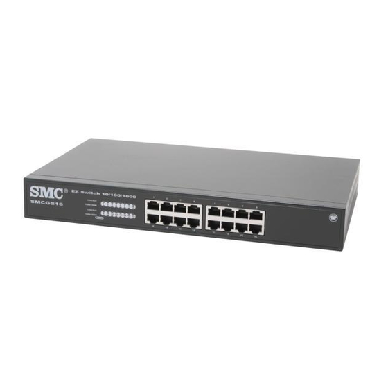
EATURES AND ENEFITS NTRODUCTION The EZ Switch 10/100/1000, SMCGS16-Smart and SMCGS24-Smart, are high performance web managed smart switches for delivering performance and control to your network. They provide 16/24 full-duplex 1000BASE-T ports that significantly improve network performance and boost throughput using Smart features configured on the web interface. -
Page 18: Initial Configuration
The following procedure is recommended: 1. Place your Smart Switch close to the PC that you will use to configure it. It will help if you can see the front panel of the switch while working on your PC. - Page 19 6. Click on the SYSTEM menu-choice then click on LAN Settings when it appears. On the LAN Settings page, enter the IP address, Subnet Mask and Gateway IP Address for the switch then click on the APPLY button. No other configuration changes are required at this stage but it is recommended that you change the administrator’s password before...
-
Page 20: Configuring The Switch
(Internet Explorer 5.5 or above, or Mozilla Firefox 1.0 or above). Prior to accessing the switch from a web browser, be sure you have first performed the following tasks: 1. Configure the switch with a valid IP address, subnet mask, and default gateway. -
Page 21: Navigating The Web Browser Interface
The Main Menu links are used to navigate to other menus, and display configuration parameters and statistics. Note: The examples in this chapter are based on the SMCGS16-Smart. Other than the number of fixed ports, there are no major differences between the SMCGS16-Smart and SMCGS24-Smart. -
Page 22: Configuration Options
“Every visit to the page.” Panel Display The web agent displays an image of the switch’s ports. The port will turn green when the corresponding front-panel port is in connection with another device. To show the port number, place mouse pointer onto the intended port. -
Page 23: Main Menu
Main Menu Using the onboard web agent, you can define system parameters, manage and control the switch, and all its ports, or monitor network conditions. The following table briefly describes the selections available from this program. Menu STATUS Overview Statistics... -
Page 24: Web Configuration
Field Attributes System Information • System Name – Name assigned to the switch system. • Number of Ports – Number of built-in ports. • Hardware Version – Hardware version of the main board. • Code Version – Version number of the code. - Page 25 • Trunk – The trunk label. "T1" through "T8" are used as trunk labels. • Type – All trunks and ports on this switch are 10/100/1000M • Trunk Status – An indication of the speed and duplex setting of the...
- Page 26 ONFIGURING THE WITCH trunk. This is a number, the speed in Mbps, followed by either “Full” for full-duplex or “Half” for half-duplex. This can be changed on the TRUNKS > Settings page. • Ports – The ports that are members of the trunk. VLAN Inoformation •...
- Page 27 ONFIGURATION Web – Click STATUS, Overview. Figure 3 Switch Information...
-
Page 28: Showing Port Statistics
Showing Port Statistics You can display statistics on network traffic from the ports. These statistics can be used to identify potential problems with the switch (such as a faulty port or unusually heavy loading). All values displayed have been accumulated since the last system reboot, but can be reset to zero by clicking the CLEAR button. - Page 29 Table 4 Port Statistics (Continued) Parameter Received Broadcast Packets Transmitted Octets Transmitted Unicast Packets Transmitted Errors Received Normal Priority Packets Transmitted Normal Priority Packets RMON Statistics Drop Events Received Frames Multicast Frames Undersize Frames Fragments Collisions Description The number of packets, delivered by this sub-layer to a higher (sub-)layer, which were addressed to a broadcast address at this sub-layer.
- Page 30 ONFIGURING THE WITCH Parameter Received Bytes Broadcast Frames CRC/Alignment Errors Oversize Frames Jabbers 64 Bytes Frames 65-127 Byte Frames 128-255 Byte Frames 256-511 Byte Frames 512-1023 Byte Frames 1024-1518 Byte Frames 1519-1536 Byte Frames Table 4 Port Statistics (Continued) Description Total number of bytes of data received on the network.
-
Page 31: Displaying System Name
ONFIGURATION Web – Click STATUS, Statistics. Figure 5 Port Statistics Displaying System Name You can easily identify the system by displaying the device name. Field Attributes • Switch Name – Name assigned to the switch system. -
Page 32: Setting The Switch's Ip Address
Setting the Switch’s IP Address This section describes how to configure an IP interface for management access over the network. The IP address for this switch is 192.168.2.10 by default. To manually configure an address, you need to change the switch’s default settings (IP address 192.168.2.10 and netmask 255.255.255.0) to... -
Page 33: Configuring The Logon Password
Manual Configuration Web – Click System, LAN Settings. Enter the IP address, subnet mask and gateway, then click APPLY. Configuring the Logon Password The administrator has write access for all parameters governing the onboard agent. You should therefore assign a new administrator password as soon as possible, and store it in a safe place. -
Page 34: Tools
APPLY. Tools On Tools page, you can restore the switch to default settings, upgrade the firmware of the switch, or restart the switch. Restore to Factory Defaults Force the Switch to restore the original factory settings. - Page 35 Figure 9 Reset to Factory Defaults Upgrade Firmware Upgrades the Switch system firmware using a file provided by SMC. Select "Upgrade Firmware" from the Tools drop-down list then click on the "Browse" button to select the firmware file. Finally, press the APPLY button to upgrade the selected Switch firmware file.
-
Page 36: Register Product
• Speed/Duplex – Allows you to manually set the port speed and duplex mode. • Flow Control – Allows flow control to be enabled or disabled. When the box is checked, flow control is enabled. Figure 11 Restart Switch Figure 12 Register Product... -
Page 37: Configuring Rate Limits
Rate limiting is configured on interfaces at the edge of a network to limit traffic into or out of the switch. Traffic that falls within the rate limit is transmitted, while packets that exceed the acceptable amount of traffic are dropped. - Page 38 Web – Click PORTS, Rate Limiting. This page enables you to set the rate limiting parameters for each port on the Switch. Figure 14 Rate Limiting...
-
Page 39: Port Broadcast Control
The same percentage threshold is applied to every port on the switch. When the threshold is exceeded, packets are dropped, irrespective of the flow control settings. -
Page 40: Port Mirroring
If the total ingress bandwidth exceeds the mirror port's egress bandwidth, packets will eventually be dropped on ingress to the switch which means they will not reach the mirror port or their intended destination port. Input rate-limiting in conjunction with port flow-control could be used to ensure that the total ingress bandwidth never exceeds the egress bandwidth. -
Page 41: Trunks Membership
This is the default state. • Trunk T1-T8 – These columns correspond to the eight trunks that are supported by the Switch. Clicking on the radio button in any one of these columns causes the port to become a member of the corresponding trunk. -
Page 42: Trunk Configuration
ONFIGURING THE WITCH Web – Click TRUNKS, Membership. Click to select which Trunk member to which each port belongs. Trunk Configuration Field Attributes • Trunk – Indicates trunk identification. • Speed/Duplex – Allows you to manually set the port speed and duplex mode for all ports in the trunk. -
Page 43: Trunk Rate Limit
Web – Click TRUNKS, Settings. Trunk Rate Limit This page allows you to change the maximum data-rate into and out of each trunk on the switch. Field Attributes • Trunk – Indicates trunk identification. • Trunk Speed – Indicates the trunk speed. -
Page 44: Vlan Settings
VLAN settings in the default configuration. The default configuration is as follows: • All ports are members of VLAN 1 • The switch management interface is on VLAN 1 (this cannot be changed) • All ports have a Port VLAN ID (PVID) of 1... - Page 45 VLAN 1. You can add up to seven VLANs to the configuration of the switch. Each VLAN must be given a VLAN ID in the range 2-4094. One port can be a member of up to eight VLANs. All packets travelling through the switch are associated with one and only one VLAN.
- Page 46 ONFIGURING THE WITCH tagged or untagged frames, or only tagged frames. When set to receive all frame types, any received frames that are untagged are assigned to the default VLAN. PCs should be connected to ports with Packet Type set to “All”.
-
Page 47: Qos Settings
QoS (Quality of Service) is a mechanism which is used to prioritize certain traffic as it is moves through the switch. Traffic can be classified as High or Normal priority and, when the switch is heavily loaded, it is the Normal priority packets that are dropped first. - Page 48 ONFIGURING THE WITCH table appears and you are able to select up to ten IP Ports for prioritization. Prioritized port numbers can be in the range 0 - 65535 inclusive. The specified ports will be given either normal or high priority depending on the value selected in the Priority drop-down list.
- Page 49 ONFIGURATION Web – Click QOS, Settings. In QoS Mode, select QoS Diabled, 802.1p, IP Port, or DSCP to configure the related parameters. Figure 21 QoS Settings...
-
Page 50: Troubleshooting
• Switch port, network card or cable may be defective. Possible Solutions • Check that the switch and attached device are both powered on. • Be sure the network cable is connected to both devices. • Verify that Category 5 or better cable is used for 10/100 Mbps connections, Category 5 or 5e cable for 1000 Mbps connections, and that the length of any cable does not exceed 100 meters (328 feet). - Page 51 If you have forgotten the administration password you can return the Switch to its factory default state by dong the following: 1. Remove the power cord from the back of the Switch. 2. Remove all cables from the front-panel ports.
-
Page 52: Changing Pc's Ip Address
PC’ IP A HANGING HANGING To change the IP address of your PC: 1. On Windows, go to Start, Settings, Network and Dial-up Connections. 2. Right-click the connectin icon of which the IP address you want to change, and then click properties. 3. - Page 53 10BASE-T: 100-ohm Category 3 or better twisted-pair 100BASE-TX: 100-ohm Category 5 or better twisted pair 1000BASE-T: 100-ohm Category 5, 5e, or 6 twisted-pair Number of Ports SMCGS16-Smart: 16 RJ-45 1000BASE-T ports SMCGS24-Smart: 24 RJ-45 1000BASE-T ports Indicator Panel Power Ports: Link/Act, 100/1000M Dimensions 33 x 20.4 x 4.4 cm (12.99 x 8.04 x 1.73 in.)
- Page 54 SMCGS16-Smart: 2.0 kg (4.04 lbs) SMCGS24-Smart: 2.2 kg (4.85 lbs) MAC Address Table 8 K entries Memory Buffer SMCGS16-Smart: 272 Kbits on-chip frame buffer SMCGS24-Smart: 400 Kbits on-chip frame buffer Power Consumption SMCGS16-Smart: 15.8 Watts SMCGS24-Smart: 24.2 Watts Heat Dissipation...
- Page 56 886-2-8797-8006 (65) 238 6556 82-2-553-0860 81-45-224-2332 61-2-8875-7887 91-22-8204437 Model Numbers: SMCGS16-Smart, SMCGS24-Smart Publication Number: 149100007600H E082005-R01 Fax (949) 679-1481 Fax 34-93-477-3774 Fax 44 (0) 1234 831 413 Fax 33 (0) 45 34 68 58 Fax 39 02 739 14 17...