
Related Manuals for Simplicity Cobalt 2690479


Summary of Contents for Simplicity Cobalt 2690479
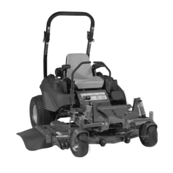
- Page 1 OPERATOR’S MANUAL Cobalt Series 27HP Zero-Turn Riders Mfg. No. Description 2690479 Simplicity 27HP Cobalt Zero-Turn Rider with 61” Mower 5100724 Revision B Rev. Date: 04/2009 TP 100-7293-B-CB-S...
- Page 2 Thank you for purchasing this quality-built Simplicity product. We’re pleased that you’ve placed your confidence in the Simplicity brand. When operated and maintained according to the instructions in this manual, your Simplicity product will provide many years of dependable service.
-
Page 3: Table Of Contents
Table of Contents Safety Rules & Information ...2 Identification Numbers ...11 Safety Decals ...12 Safety Icons & Interlock System...13 Features & Controls ...14 Control Functions...14 Operation ...16 General Operating Safety ...16 Checks Before Starting ...16 Starting the Engine ...17 Stopping the Rider ...17 Pushing the Rider by Hand...17 Zero Turn Driving Practice ...18 Raise &... -
Page 4: Safety Rules & Information
Safety Rules and Information Read the Manual The operator’s manual contains important safety information you need to be aware of BEFORE you operate your unit as well as DURING operation. Safe operating techniques, an explanation of the product’s features and controls, and maintenance information is included to help you get the most out of your equipment investment. -
Page 5: Slope Operation
Thrown Objects This unit has spinning mower blades. These blades can pick up and throw debris that could seriously injure a bystander. Be sure to clean up the area to be mowed and remove objects that could be thrown by the blade BEFORE you start mowing. -
Page 6: Safety Rules And Information
Safety Rules and Information Retaining Walls, Drop- offs, and Water Retaining walls and drop-offs around steps and water are a common hazard. Give yourself a minimum of two mower widths of clearance around these hazards and hand-trim with a walk behind mower or string trimmer. - Page 7 Enclosed Areas Only operate this unit outdoors and away from unventilated areas such as inside garages or enclosed trailers. The engine emits poisonous carbon monoxide gas and prolonged exposure in an enclosed area can result in serious injury or death. Safety Rules and Information Fuel and Maintenance Always disengage all drives, shutoff the engine, and...
- Page 8 Safety Rules and Information Read these safety rules and follow them closely. Failure to obey these rules could result in loss of control of unit, severe personal injury or death to you, or bystanders, or damage to property or equipment. This mowing deck is capable of amputating hands and feet and throwing objects. The triangle in text signifies important cautions or warnings which must be followed.
- Page 9 SLOPE OPERATION Slopes are a major factor related to loss-of-control and tip-over accidents, which can result in severe injury or death. Operation on all slopes requires extra caution. If you cannot back up the slope or if you feel uneasy on it, do not operate on it.
- Page 10 Safety Rules and Information SERVICE AND MAINTENANCE Safe Handling of Gasoline 1. Extinguish all cigarettes, cigars, pipes, and other sources of ignition. 2. Use only approved gasoline containers. 3. Never remove the gas cap or add fuel with the engine running. Allow the engine to cool before refueling.
- Page 11 ROLL BAR INSTRUCTIONS For models equipped with factory-installed Roll Over Protection System (ROPS). WARNING In order to avoid serious injury or death from roll over, it is important to follow the warnings listed below. OPERATIONAL WARNINGS • Always use the seat belt when the roll bar is in the raised position.
- Page 12 Safety Rules & Information WARNING Failure to properly inspect and maintain the seat belt can cause serious injury or death. INSPECTION AND MAINTENANCE OF THE ROLL BAR SEAT BELT • The seat belt like the ROLL BAR, needs to be periodically inspected to verify that the integrity has not been compromised through normal machine use, misuse, age degradation,...
-
Page 13: Identification Numbers
XXXX LpA: XXX dB(A) Vibration @ Wheel: XXX m/s² Vibration @ Seat: XXX m/s² Simplicity Mfg. Inc. Port Washington, WI USA 53074-0997 XXXXXXX When contacting your authorized dealer for replacement parts, service, or information you MUST have these numbers. Record your model name/number, manufacturer’s identification numbers, and engine serial numbers in the space provided for easy access. -
Page 14: Safety Decals
Safety Decals SAFETY DECALS This unit has been designed and manufactured to provide you with the safety and reliability you would expect from an industry leader in outdoor power equipment manufacturing. Although reading this manual and the safety instructions it contains will provide you with the necessary basic knowledge to operate this equipment safely and effectively, we have placed several safety labels on the unit to remind you of this important... -
Page 15: Safety Icons & Interlock System
SAFETY INTERLOCK SYSTEM This unit is equipped with safety interlock switches. These safety systems are present for your safety, do not attempt to bypass safety switches, and never tamper with safety devices. Check their operation regularly. Operational SAFETY Checks Test 1 — Engine should NOT crank if: •... -
Page 16: Features & Controls
Features & Controls CONTROL FUNCTIONS The information below briefly describes the function of individual controls. Starting, stopping, driving, and mowing require the combined use of several controls applied in specific sequences. To learn what combination and sequence of controls to use for various tasks see the OPERATION section. Deck Lift Pedal, Cutting Height Adjustment Pin &... - Page 17 Ignition Switch The ignition switch starts and stops the engine, it has three positions: Stops the engine and shuts off the electrical system. Allows the engine to run and powers t the electrical system. START Cranks the engine for starting. NOTE: Never leave the ignition switch in the RUN position with the engine stopped–this drains the battery.
-
Page 18: Operation
Operation GENERAL OPERATING SAFETY Before first time operation: • Be sure to read all information in the Safety and Operation sections before attempting to operate this tractor and mower. • Become familiar with all of the controls and how to stop the unit. -
Page 19: Starting The Engine
WARNING If you do not understand how a specific control functions, or have not yet thoroughly read the FEATURES & CONTROLS section, do so now. Do NOT attempt to operate the tractor without first becoming familiar with the location and function of ALL controls. -
Page 20: Zero Turn Driving Practice
Operation ZERO TURN DRIVING PRACTICE The lever controls of the Zero Turn rider are responsive, and learning to gain a smooth and efficient control of the rider’s forward, reverse, and turning movements will take some practice. Spending some time going through the maneuvers shown and becoming familiar with how the unit accelerates, travels, and steers —... -
Page 21: Advanced Driving
Practice Turning Around a Corner While traveling forward allow one handle to gradually return back toward neutral. Repeat several times. NOTE: To prevent pivoting directly on the tire tread, it is best to keep both wheels going at least slightly forward. -
Page 22: Raise & Lower The Roll Bar
Operation RAISE & LOWER THE ROLL BAR WARNING AVOID SERIOUS INJURY OR DEATH FROM ROLL OVER: Keep roll bar in the raised position and use seat belt. THERE IS NO ROLL OVER PROTECTION WHEN THE ROLL BAR IS DOWN Lower the roll bar only when necessary and NEVER remove it. -
Page 23: Mowing
MOWING Before mowing, set the cutting height as described in the Troubleshooting, Adjustments & Service section. 1. Engage the parking brake. Make sure the PTO switch is disengaged and the motion control lever is in the NEUTRAL position. 2. Start the engine (see STARTING THE ENGINE). 3. -
Page 24: Mowing Methods
Operation When and How Often to Mow The time of day and condition of the grass greatly affect the results you’ll get when mowing. For the best results, follow these guidelines: 1. Mow when the grass is between three and five inches high. -
Page 25: Attaching A Trailer
Proper Mulching Mulching consists of a mower deck which cuts and recuts clippings into tiny particles and which then blows them down INTO the lawn. These tiny particles decompose rapidly into by-products your lawn can use. UNDER PROPER CONDITIONS, your mulching mower will virtually eliminate noticeable clippings on the lawn surface. -
Page 26: Regular Maintenance
Regular Maintenance MAINTENANCE SCHEDULE The following schedule should be followed for normal care of your rider and mower. You will need to keep a record of your operating time. Determining operating time is easily accomplished by observing the elapsed time recorded by the hour meter. -
Page 27: Checking Tire Pressures
CHECK TIRE PRESSURES Tire pressure should be checked periodically, and maintained at the levels shown in the chart. Note that these pressures may differ slightly from the “Max Inflation” stamped on the side-wall of the tires. The pressures shown provide proper traction, improve cut quality, and extend tire life. -
Page 28: Check Hydraulic Oil Level
NOTE: Removing the oil filter from the filter base will drain the oil reservoir. Have a suitable container ready to catch any spilled oil. Simplicity recommends this be a dealer-only service item. 1. Locate the transmission oil filter (A, Figure 17). -
Page 29: Lubrication
LUBRICATION Lubricate the unit at the locations shown in Figures 18 through 22 as well as the following lubrication points. Grease: • front caster wheel axles & yokes • deck lift pivot blocks • mower deck spindles • mower deck idler arm Use grease fittings when present. -
Page 30: Battery Maintenance
Regular Maintenance BATTERY MAINTENANCE NOTE: This unit is equipped with a maintenance-free BCIU1 battery. Cleaning the Battery and Cables 1. Remove the hydraulic oil reservoir mounting hardware (C, Figure 23) and move the reservoir (D) forward to expose the battery. 2. -
Page 31: Servicing The Mower Blades
SERVICING THE MOWER BLADES 1. Blades should be sharp and free of nicks and dents. If not, sharpen blades as described in the following steps. 2. To remove blade for sharpening, use a 1” wrench on the flats of the spindle shaft while removing the blade mounting bolt with a 15/16”... -
Page 32: Troubleshooting, Adjustments & Service
Troubleshooting, Adjustment & Service TROUBLESHOOTING While normal care and regular maintenance will extend the life of your equipment, prolonged or constant use may eventually require that service be performed to allow it to continue operating properly. The troubleshooting guide below lists the most common problems, their causes and remedies. -
Page 33: Troubleshooting The Mower
Rider Troubleshooting Continued. PROBLEM Engine runs, but rider will not drive. Rider drive belt slips. Brake will not hold. Rider steers or handles poorly. TROUBLESHOOTING THE MOWER PROBLEM Mower will not raise. Engine stalls easily with mower engaged. Excessive mower vibration. Excessive belt wear or breakage. -
Page 34: Troubleshooting Common Cutting Problems
Troubleshooting, Adjustment & Service TROUBLESHOOTING COMMON CUTTING PROBLEMS PROBLEM Streaking. Scalping. Stepped Cutting. Uneven Cutting. Stingers. CAUSE 1. Blades are not sharp. 2. Blades are worn down to far. 3. Engine speed is too slow. 4. Ground speed is too fast. 5. -
Page 35: Seat Adjustment
SEAT ADJUSTMENT See Figure 27. The seat can be adjusted forward and back. Move the lever (A) forward, position the seat as desired, and release the lever to lock the seat into position. GROUND SPEED CONTROL LEVER ADJUSTMENT The control levers can be adjusted in three ways. The alignment of the control levers, the placement of the levers (how close the ends are to one another) and the height of the levers can be adjusted. -
Page 36: Neutral Adjustment
Troubleshooting, Adjustment & Service NEUTRAL ADJUSTMENT If the tractor “creeps” while the ground speed control levers are locked in NEUTRAL, then it may be necessary to adjust the linkage rod. NOTE: Perform this adjustment on a hard, level surface such as a concrete floor. 1. -
Page 37: Parking Brake Adjustment
PARKING BRAKE ADJUSTMENT 1. Disengage the PTO, engage the parking brake, stop the engine and remove the ignition key. 2. Raise the seat plate. 3. Locate the brake spring (A, Figure 32). 4. With the parking brake engaged, measure the compressed spring length. -
Page 38: Suspension Adjustment
Troubleshooting, Adjustment & Service SUSPENSION ADJUSTMENT The shock assembly can be adjusted to vary the amount of pre-load applied to the springs. This allows the operator to maintain the ride height. Use less pre-load for light weight operators. Use more pre-load for heavy weight operators. -
Page 39: Mowing Height Adjustment
MOWING HEIGHT ADJUSTMENT The cutting height adjustment pin (A, Figure 34) controls the mower cutting height. The cutting height is adjustable between 1-3/4” (4,4 cm) and 5” (12,7 cm) in 1/4” (0,64 cm) increments. 1. Depress the deck lift foot pedal (B) until it locks into the 5”... -
Page 40: Deck Lift Rod Timing Adjustment
Troubleshooting, Adjustment & Service DECK LIFT ROD TIMING ADJUSTMENT 1. Park machine on a flat, level surface. Disengage the PTO, stop the engine and engage the parking brake. Rear tires must be inflated to 18 psi (1,24 bar); front tires to 25 psi (1,72 bar). 2. -
Page 41: Deck Leveling Adjustment
DECK LEVELING ADJUSTMENT NOTE: Before adjusting the deck level, the deck lift rod timing must be checked and/or adjusted. 1. Park machine on a flat, level surface. Disengage the PTO, stop the engine and engage the parking brake. Rear tires must be inflated to 15 psi (1,03 bar);... -
Page 42: Hydraulic Pump Drive Belt Replacement
Troubleshooting, Adjustment & Service HYDRAULIC PUMP DRIVE BELT REPLACEMENT 1. Park the tractor on a smooth, level surface such as a concrete floor. Disengage the PTO, engage the parking brake, turn off the engine, and remove the ignition key. 2. Remove the PTO drive belt (see MOWER BELT REPLACEMENT for removal instructions). -
Page 43: Mower Belt Replacement
MOWER BELT REPLACEMENT To avoid damaging belts, DO NOT PRY BELTS OVER PULLEYS. 1. Park the tractor on a smooth, level surface such as a concrete floor. Disengage the PTO, engage the parking brake, turn off the engine, and remove the ignition key. -
Page 44: Battery Service
Troubleshooting, Adjustment & Service BATTERY CHARGING A dead battery or one too weak to start the engine may be the result of a defect in the charging system or other electrical component. If there is any doubt about the cause of the problem, see your dealer. If you need to replace the battery, follow the steps under Cleaning the Battery &... -
Page 45: Specifications
For applicable manuals currently available for your model, contact our Customer Publications Department at 262-284-8519 (Simplicity). Have the information listed in the box below available when phoning in your request. Technical manuals can be downloaded from www.simplicitymfg.com factors. - Page 46 Notes www.simplicitymfg.com...
- Page 48 Product Quick Specs: ENGINE: 27 HP* Kohler Make Kohler Model CV740S Horsepower 27 @ 3600 rpm Displacement 44.24 Cu. in (725 cc) Electrical System 12 Volt, 16 amp. Alternator, Battery: 340 Oil Capacity 4.2 pt. (2.0 L) w/ Filter CHASSIS: Fuel Tank Capacity: 11 Gallons (41.6 L) Total Rear Wheels...