
Related Manuals for Siemens E-110


Summary of Contents for Siemens E-110
-
Page 1: User Manual
SIEMENS ADSL E-110/E-110-I ETH & USB ComboRouter User Manual Rev:01_040220 2004-02-20 No part of this publication may be reproduced in any form by any means without the prior written permission from Siemens Switzerland Ltd... -
Page 2: Safety Notes
Safety Notes For Installation Use only the type of power source indicated on the marking labels. Use only the power adapter supplied with the product. Do not overload wall outlet or extension cables as this may increase the risk of electric shock or fire. If the power cable is frayed, replace it with a new one. -
Page 3: Table Of Contents
Content Safety Notes... i Safety Notes... ii For Installation... ii For Using ... ii For Service ... ii Warning... ii Caution... ii Content ... iii Before You Use... 1 Features ... 1 System Requirements... 2 Unpacking ... 2 Chapter 1: Overview ... 3 Physical Outlook ... - Page 4 Advanced Configuration via Web browser ... 33 Main Menu ... 34 Commonly Used Buttons and Icons... 34 Viewing Basic System Information... 35 Quick Configuration ... 36 Committing Changes to Permanent Storage ... 37 Rebooting the device using Configuration Manager... 37 Sub-Menus...
-
Page 5: Content
Appendix: Specification... 83 Software ... 83 Hardware ... 84 Rev:01_040220... -
Page 7: Before You Use
The SIEMENS ADSL E-110/E-110-I is designed to offer cost-effective high-speed services for home or office users. It provides a downstream rate of up to 8 Mbps and upstream rate of up to 1 Mbps for ADSL connection, even offers auto-negotiation capability for different flavors (ANSI T1.413 Issue 2, G.lite, G.dmt... -
Page 8: System Requirements
Configuration and Management DSL Forum TR37-compliant auto configuration SNMPv1 over DSL or Ethernet for access to the MIB-II (router only) CLI (Command Line Interface) via serial interface or Telnet over Ethernet or DSL Web-based Graphical User Interface (GUI) enabling end-user device configuration via Web browser Update of boot image configuration data over TFTP/FTP System Requirements For using this, you have to make sure you have the following that installed on the clients:... -
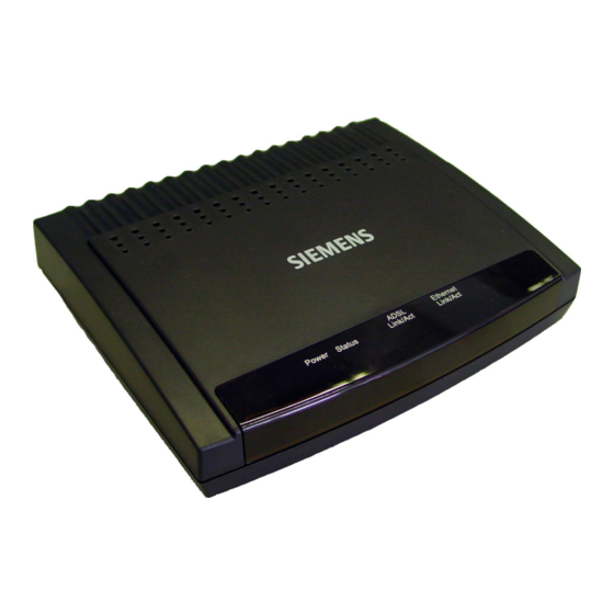
Page 9: Chapter 1: Overview
Chapter 1: Overview Physical Outlook Physical Outlook Front Panel The following illustration shows the front panel of the ADSL Router: LED Indicators (Front Panel System Messages) The ADSL Router is equipped with orange LEDs on the front panel as described in the table below (from left to right): Status Description... -
Page 10: Rear Panelrear Panel
Rear PanelRear Panel The following figure illustrates the rear panel of your ADSL Router. ADSL Connects the device to an ADSL telephone jack using the supplied cable. Connects the device to the USB port on your PC. Ethernet Connects the device to your PC's Ethernet port, or to the uplink port on your LAN's hub, using the cable provided. -
Page 11: Chapter 2: Installation
Analog (PSTN) installation If your telephone service is analog (SIEMENS ADSL E-110), proceed as follows to install your Hardware: Remove the end of the phone line from your phone connector and plug it into the “LINE” plug of the PSTN Microfilter. -
Page 12: Isdn Installation
ISDN installation If your telephone service is ISDN (SIEMENS ADSL E-110-I), proceed as follows to install your Hardware: Remove the U-Line (incoming line) form your ISDN NT and plug it into the “LINE” plug of the ISDN Splitter. Use another phone line to connect your ISDN NT with your ISDN Splitter. Plug this phone line onto the “PHONE”... -
Page 13: Usb Driver Installation
1b. Do NOT connect your ADSL router to your computer now. Turn on your computer. Insert the Siemens installation CD-ROM in your CD-ROM drive. The installation procedure will start automatically and the following window appears: Note: In case the setup wizard does not start automatically, open a “Run” window via “Start”... -
Page 14: Uninstall The Usb Driver
The Reboot window indicates successful completion of the uninstall process. Remove any disks from the drives. Select the Yes, reboot the computer now option by clicking in the radio button to its left, and click Close. Siemens DSL Modem Uninstall. Rev:01_040220... -
Page 15: Chapter 3: Configuration
Chapter 3: Configuration In order to access the Internet through the router, you must check the TCP/IP settings before configuring the router. Step 1: Configure TCP/IP on Client PC To access the ADSL Router via Ethernet, the host computer must meet the following requirements: With Ethernet network interface. - Page 16 Double-click the Network icon. The Network window appears. On the Configuration tab, check out the list of installed network components. Option 1: If you have no TCP/IP protocol, click [Add]. Option 2: If you have TCP/IP protocol, go to Step 6. Highlight Protocol and click [Add].
- Page 17 On the left side of the windows, highlight Microsoft and then select TCP/IP on the right side. Then click [OK]. When returning to Network window, highlight TCP/IP protocol for your NIC and click [Properties]. On IP Address tab, select Obtain an IP address automatically. Then click [OK]. Rev:01_040220...
- Page 18 When returning to Network window, click [OK]. Windows may ask you for the original Windows installation disk or additional files. Insert the Windows 95 installation CD-ROM and click [OK]. 10. Supply the requested files by pointing to the correct location, e.g. D:\Win95, where “D” represents the letter of your CD-ROM drive.
-
Page 19: For Windows 98 And Windows 98 Se
For Windows 98 and Windows 98 SE Note: Windows 98 and 98 SE users need the Windows 98 / Windows 98 SE installation CD-ROM to complete the installation! Click on the Start menu, point to Settings and click on Control Panel. Double-click the Network icon. - Page 20 The Network window appears. On the Configuration tab, check out the list of installed network components. Option 1: If you have no TCP/IP protocol, click [Add]. Option 2: If you have TCP/IP protocol, go to Step 6. Highlight Protocol and click [Add]. On the left side of the windows, highlight Microsoft and then select TCP/IP on the right side.
- Page 21 When returning to Network window, highlight TCP/IP protocol for your NIC and click [Properties]. On IP Address tab, select Obtain an IP address automatically. Then click [OK]. When returning to Network window, click [OK]. Rev:01_040220...
- Page 22 Windows may ask you for the original Windows installation disk or additional files. Insert the Windows 95 installation CD-ROM and click [OK]. 10. Supply the requested files by pointing to the correct location, e.g. D:\Win95, where “D” represents the letter of your CD-ROM drive. 11.
-
Page 23: For Windows Me
For Windows ME Click on the Start menu, point to Settings and click on Control Panel. Double-click the Network icon. The Network window appears. On the Configuration tab, check out the list of installed network components. Option 1: If you have no TCP/IP protocol, click [Add]. Option 2: If you have TCP/IP protocol, go to Step 6. -
Page 24: For Windows Nt
For Windows NT Note: Windows NT users need the Windows NT installation CD-ROM to complete the installation! Click Start, point to Settings and then click Control Panel. Double-click the Network icon. The Network window appears. On the Protocols tab, check out the list of installed network components. - Page 25 Highlight TCP/IP Protocol and click [OK]. Click [Yes] to use DHCP. Insert the Windows NT CD into your CD-ROM drive and type the location of the CD. Then click [Continue]. Returning to the Network window, you will find the TCP/IP Protocol among the list. Click on [Close]. When prompted with Network Settings Change dialog box, click [Yes] to restart your computer.
- Page 26 SIEMENS ADSL E-110_E-110-I user manual Right click on the Network Neighborhood icon on the desktop and select Properties. 10. In the Protocol tab select TCP/IP Protocol and click on [Properties]. 11. Select Obtain an IP address from a DHCP server. Then click [OK].
- Page 27 Chapter 3: Configuration 13. When returning to Network window, click [OK]. Rev:01_040220...
-
Page 28: For Windows 2000
For Windows 2000 From the Start menu, point to Settings and then click Network and Dial-up Connections. Right-click the Local Area Connection icon and then click Properties. On the General tab, check out the list of installed network components. Option 1: If you have no TCP/IP Protocol, click [Install]. Option 2: If you have TCP/IP Protocol, go to Step 6. - Page 29 Highlight Protocol and then click [Add]. Click Internet Protocol(TCP/IP) and then click [OK]. When returning to Local Area Connection Properties window, highlight Internet Protocol (TCP/IP) and then click [Properties]. Rev:01_040220...
- Page 30 Under the General tab, select Obtain an IP address automatically. Then click [OK]. When prompted to restart your computer, reboot it to enable the settings. Rev:01_040220...
-
Page 31: For Windows Xp
For Windows XP From the Start menu, point to Control Panel and then click Network and Internet Connections. Click Network Connection and then click Properties. On the General tab, check out the list of installed network components. Option 1: If you have no TCP/IP Protocol, click [Install]. Option 2: If you have TCP/IP Protocol, go to Step 6. -
Page 32: For Macintosh Os 8.6 And 9.X
For Macintosh OS 8.6 and 9.x From the Apple Menu, point to Control Panels and then click TCP/IP. From the Connect via pull-down menu select Ethernet built-in. From the Configure pull-down menu select Using DHCP Server. Close the TCP/IP window and click on [Save]. Rev:01_040220... -
Page 33: For Macintosh Os 10.X
For Macintosh OS 10.x From the Apple Menu, select System Preferences… Click on Network. From the Show pull-down menu select Built-in-Ethernet. On the TCP/IP tab, select Using DHCP from the Configure pull-down menu. Rev:01_040220... - Page 34 On the PPPoE tab, and make sure that the Connect using PPPoE check box is NOT activated. Click Apply Now. Close the Network window. Rev:01_040220...
-
Page 35: Renew Ip Address On Client Pc
Renew IP Address on Client PC There is a chance that your PC does not renew its IP address after the ADSL Router is on line and the PC cannot access the Internet. Please follow the procedures below to renew PC’s IP address. Note: This feature is only available for the following operating systems: Windows 98/98 SE/ME/2000/XP! For Windows 98 and Windows 98 SE Select Run from the Start menu. -
Page 36: For Windows Me
For Windows ME Select Run from the Start menu. Type winipcfg in the dialog box and the click [OK]. When the figure below appears, click [Release] and then [Renew] to get an IP address. For Windows NT Select Run from the Start menu. Type cmd in the dialog box and the click [OK]. -
Page 37: For Windows 2000
For Windows 2000 From the Start menu, point to Programs > Accessories and then click Command Prompt. Type ipconfig at prompt. Then you will see the IP information from DHCP server. If you want to get a new IP address, type ipconfig /release to release the previous IP address and then type ipconfig /renew to get a new one. -
Page 38: Step 2: Quick Configuration Via Web Browser
Step 2: Quick Configuration via Web browser Your ADSL Router includes a Web-based Configuration Manager, which enables you to configure the device settings to meet the needs of your network. Once your host PC is properly configured, please proceed as follows: Start your Web browser and type 192.168.1.1 in the address field of your browser. -
Page 39: Advanced Configuration Via Web Browser
Chapter 3: Configuration Advanced Configuration via Web browser Note: Please follow carefully the instructions in the whole chapter in order to be sure that your PC and your ADSL Router are working properly. For advanced configuration click to Advanced Configuration. You will be prompted to enter username and password. -
Page 40: Main Menu
Main Menu Configuration Manager tasks are grouped info categories which can be accessed by clicking the main menu on the left. Each menu displays the available tasks in sub-menus. The specific configuration options are displayed by clicking on these menus. The same sub-menu may appear in more than one menu, when appropriate. -
Page 41: Viewing Basic System Information
Viewing Basic System Information System View page displays when you first access the program. System View table provides a snapshot of your system configuration. You can click on the table headings that are highlighted in orange lettering to display a more details on those settings or the configuration page for that feature. -
Page 42: Quick Configuration
Quick Configuration The Quick Configuration displays the settings you are most likely to need to change when you first set up your ADSL Router. Work with your ISP to determine the values or settings you need to change. Select Home > Quick Configuration. The Quick Configuration page contains the following fields: Field... -
Page 43: Committing Changes To Permanent Storage
Field Use DNS Primary DNS Server / Secondary DNS Server Committing Changes to Permanent Storage Whenever you change system settings, the changes are initially placed in temporary storage (called random access memory or RAM). Your changes are made effective when you submit them, but will be lost if the device is reset or turned off. -
Page 44: Sub-Menus
Sub-Menus For advanced mode, the following sub-menus are available: LAN Config Sets LAN configuration, which determines you the device is defined in the network. DHCP Mode Sets and configures the Dynamic Host Configuration Protocol mode for the device. With DHCP, IP addresses for your LAN are administrated and distributed as needed by this device or an ISP device. - Page 45 Configures and displays Point to Point Protocol (PPP) interfaces. The PPP protocol is commonly used between ISPs and their customers to identify and control various communication properties. Configures and displays RFC1483/Ethernet over ATM (EoA) interfaces. The EoA protocol is commonly used to carry data between LANs that use the Ethernet protocol and WANs that use the ATM protocol.
-
Page 46: Chapter 4: Advanced Configuration
Chapter 4: Advanced Configuration Configuring IP Routes Most users do not need to define IP routes. You may need to define routes if: Your network setup includes two or more networks or subnets. You connect to two or more ISP services. You connect to a remote corporate LAN. -
Page 47: Dhcp Configuration
DHCP Configuration You can configure your network and ADSL Router to use the Dynamic Host Configuration Protocol (DHCP). The device can be configured as a DHCP server, DHCP relay agent, or, in some cases, a DHCP client. DHCP server - It will maintain the pool of addresses and distribute them to your LAN computers. If the pool of addresses includes private IP addresses, you must also configure the Network Address Translation service, so that the private addresses can be translated to your public IP address on the Internet. - Page 48 To add an IP address pool, click [Add]. The Field Start / End IP Addresses Mac Address (optional) Netmask Domain Name (optional) The domain name to be used by DHCP clients. Gateway Address DNS Address (optional) SDSN...SWINS Address (optional) Click [Apply]. A confirmation page displays to indicate that the pool has been added successfully. Click [Close] to return to the Part 2.
- Page 49 Part 3. Configuring your PCs as DHCP clients For each computer that you want to configure to receive IP information automatically, configure the TCP/IP properties to Obtain an IP address automatically (the actual text may vary depending on your operating system).
-
Page 50: Configuring Dhcp Relay
Configuring DHCP Relay Part 1. Defining the DHCP relay interface(s) Select Lan > DHCP Relay. The This page provides a text box for entering the IP address of your ISP’s DHCP server and a table that lists the interfaces on your ADSL Router that can relay DHCP information. Type the IP address of your ISP’s DHCP server in the fields provided. -
Page 51: Nat Configuration
NAT Configuration This section provides an overview of Network Address Translation (NAT) and instructions for modifying the default configuration on your device. By default, NAT is enabled, with an network address port translation (napt) rule configured to perform the following translation: These private IP addresses: 192.168.1.2 192.168.1.3... - Page 52 NAT Global Information Field TCP Idle Timeout(sec) For a NAT translation session on data that uses the TCP protocol, the TCP Close Wait(sec) TCP Def Timeout(sec) UDP Timeout(sec) ICMP Timeout(sec) GRE Timeout(sec) Default Nat Age(sec) NAPT Port Start/End If you change any values, click [Apply]. A page gives a receipt for the changes. Select Admin >...
- Page 53 Chapter 4: Advanced Configuration On the NAT Configuration page you can click [Global Stats] to view accumulated data on how many NAT rules have been invoked and how much data has been translated. A page similar to the one below displays.
-
Page 54: Viewing Nat Rules And Rule Statistics
Viewing NAT Rules and Rule Statistics To view the NAT Rules currently defined on your system, select Services > NAT. From the NAT Options drop-down list select NAT Rule Entry. The To view data on how often a specific NAT rule has been used, click [Stats]. A page similar to the one below displays: The statistics show how many times this rule has been invoked and how many currently active sessions are using this rule. -
Page 55: Adding Nat Rules
Field Description ALG Type The Application Level Gateway (ALG), if any, that was used to enable this NAT translation (ALGs are special settings that certain applications require in order to work while NAT is enabled). NAT Direction The direction (incoming or outgoing) of the translation (from the port definition). Entry Age The elapsed time, in seconds, of the NAT translation session. - Page 56 Define the rule ID and select the interface. In the Local Address From/To fields, type the starting and ending IP addresses, respectively, of the range of private address you want to be translated. Or, type the same address in both fields to specify a single value.
- Page 57 If the publicly accessible LAN computer uses a non-standard port number for the type of traffic it receives, type the non-standard port number in the Local Port field. Complete as described for general procedure (steps 6 to 10). The basic rule: Performing 1:1 translations The basic flavor translates the private (LAN-side) IP address to a public (WAN-side) address, like napt rules.
- Page 58 On the NAT Rule - Add Define the rule ID and select the interface. From the Protocol drop-down list, select a protocol to which this rule applies, or choose ANY if the rule applies to all data. In the Local Address From/To fields, type the starting and ending IP addresses that identify the range of private address you want to be translated.
- Page 59 Bimap rules can be used to provide external access to a LAN device. They do not provide the same level of security as rdr rules, because rdr rules also reroute incoming packets based on the port ID. Bimap rules do not account for the port number, and therefore allow external access regardless of the destination port type specified in the incoming packet.
-
Page 60: Rip Configuration
RIP Configuration Your ADSL Router can be configured to communicate with other routing devices to determine the best path for sending data to its intended destination. This chapter describes how to configure your ADSL Router to use one of these, called the Routing Information Protocol (RIP). Most small home or office networks do not need to use RIP. -
Page 61: Viewing Rip Statistics
Click [Add]. The new RIP entry will display in the table. Click the Enable radio button to enable the RIP feature. When you are finished defining RIP interfaces, click [Apply]. A page gives a receipt for the changes. Select Admin > Commit & Reboot and click [Save] to save your changes to permanent storage. Viewing RIP Statistics Select to Services >... -
Page 62: Firewall, Ip Filters And Blocked Protocols
Firewall, IP Filters and Blocked Protocols Firewall Configuration Configuration Manager provides built-in firewall functions, enabling you to protect the system against denial of service (DoS) attacks and other types of malicious accesses to your LAN. You can also specify how to monitor attempted attacks, and who should be automatically notified. - Page 63 Field Max Half open TCP Conn. Max ICMP Conn. Max Single Host Conn. Log Destination E-Mail ID of Admin 1/2/3 Click [Apply]. A page gives a receipt for the changes. Select Admin > Commit & Reboot and click [Save] to save your changes to permanent storage. Rev:01_040220 Description Sets the percentage of concurrent IP sessions that can be in the...
-
Page 64: Ip Filter Configuration
IP Filter Configuration The IP filter feature enables you to create rules that control the forwarding of incoming and outgoing data between your LAN and the Internet. This chapter explains how to create IP filter rules. Viewing Your IP Filter Configuration Select Services >... - Page 65 Creating IP Filter Rules On the IP Filter Configuration Enter or select data for each field that applies to your rule: Field Description Rule ID Rules are processed from lowest to highest on each data packet, until a match is found.
- Page 66 Field Description Log Option When Enabled is selected, a log entry will be created on the system each time this rule is invoked. Security Level The security level that must be enabled globally for this rule to take affect. A rule will be active only if its security level is the same as the globally configured setting (shown on the main IP Filter page).
- Page 67 Field Description Dest Port Port number criteria for the destination computer(s) (i.e., the port number of the type of computer to which the packet is being sent). This field will be dimmed (unavailable for entry) unless you have selected TCP or UDP as the protocol.
- Page 68 IP filter rule examples Example 1. Blocking a specific computer on your LAN from using accessing Web servers on the Internet: Add a new rule for outgoing packets on the ppp-0 interface from any incoming interface (this would include the eth-0, for example). Specify a source IP address of the computer you want to block.
- Page 69 The figure below shows how this rule could be configured: Viewing IP Filter Statistics Select Services > IP Filter. The To view statistics on how many packets were accepted or denied for a rule, click [Stats] in the row corresponding to the rule: Rev:01_040220 IP Filter Configuration page displays.
-
Page 70: To Block Specific Protocols
Managing Current IP Filter Sessions Select Services > IP Filter. The To view all current IP sessions, click [Session]. The It displays the following fields: Field Description Session Index The ID assigned by the system to the IP session (all sessions, whether or not they are affected by an IP filter rule, are assigned a session index). -
Page 71: Administration Tasks
Administration Tasks Changing the System Date and Time The device keeps a record of the current date and time, which it uses to calculate and report various performance data. Select Home. The System View Click [Modify] to change the date and time as required. Click [Apply]. -
Page 72: Image Upgrade
Adding a New User Select Admin > User Config. The Click [Add]. The User Config - Add Enter a new username in the User ID text box. It can be up to 128 characters and is case-sensitive. Select the desired Privilege. Type the password in the Password text box and again in the Confirm New text box. -
Page 73: View System Alarms
View System Alarms To display the Alarm page, select Admin > Alarm. Each row in the table displays the time and date that an alarm occurred, the type of alarm, and a brief statement indicating its cause. You can click on the Refresh Rate drop-down list to select a recurring time interval after which the page will redisplay with new data. -
Page 74: Port Settings
Port Settings The router’s HTTP service (Web Configuration Utility), Telnet service and FTP service are accessible using the standard port number 80, 23 and 21 respectively. It is possible that you want to designate a publicly accessible HTTP, Telnet or FTP server on your LAN side and you want to shift the router’s HTTP/Telnet/FTP service to use non-standard port number. -
Page 75: View Dsl Parameters
View DSL Parameters To view configuration parameters and performance statistics for the ADSL Router’s DSL line, select WAN > DSL Status. The DSL Status page displays current information on the DSL line performance. The page refreshes about every 10 seconds (Refresh Rate). You can click [DSL Param] to display data about the configuration of the DSL line, as shown below. - Page 76 SIEMENS ADSL E-110_E-110-I user manual From the DSL Status page, you can click [Stats] to display DSL line performance statistics: DSL Statistics page reports error data relating to the last 15 minute interval, the current day, and the previous day.
-
Page 77: Chapter 5: Connection Modes
Chapter 5: Connection Modes The ADSL Router is delivered pre-configured from the factory in Router Mode. This chapter presents some deployment examples for your reference. Each mode includes its general configure procedures. For more detailed information about Web configuration, refer to chapters 3 and 4. Bridge Mode PPP Connection Mode Router Mode... - Page 78 Enter the provided fields as below. Field VC Interface VPI / VCI Mux Type Max Proto per AAL5 After entering the fields above, click [Apply]. When confirmation page appears, click [Close]. You will return to the ATM VC Configuration 2. Creating an EoA interface. Select Bridge >...
- Page 79 When confirmation page appears, click [Close]. You will return to the ATM(EoA) Config 3. Enable Bridging function. Select Bridge > Bridging to display the Select eth-0 from the list and click [Add]. Select the EoA interface to be used (e.g. eoa-0) from the drop-down list, and then click [Add]. Make sure Enable is selected for Bridging.
-
Page 80: Part 2: Check Your Connection Status
5. Commit your changes. Select Admin > Commit & Reboot and click [Save] to save your changes to permanent storage. Part 2: Check your connection status. Select Home. On the System View created to communicate with your ISP. A green ball in the Status field indicates a successful connection. Part 3: Configuring the PC. - Page 81 Enter the provided fields as below: Field VC Interface VPI / VCI Mux Type Max Proto per AAL5 After entering the fields above, click [Apply]. When confirmation page appears, click [Close]. You will return to the ATM VC Configuration 2. Creating a PPP interface. Select Wab >...
-
Page 82: Part 2: Check Your Connection Status
Field Status Protocol Service Name Use DHCP Use DNS Default Route Security Protocol Login Name Password After entering the fields above, click [Apply]. When confirmation page appears, click [Close]. You will return to the PPP Configuration The Oper. Status Link Up indicates the link is currently up. Part 2: Check your connection status. -
Page 83: Router Connection Mode
Router Connection Mode In this deployment environment, we make up a private IP network of 192.168.1.1. NAT function is enabled (on ADSL Router or use another NAT box connected to hub) to support multiple clients to access the Router and some public servers (WWW, FTP). If you apply for multiple IP addresses from your ISP, you can assign these public IP addresses to the ADSL Router and public server, e.g., Web or FTP server. -
Page 84: Part 2: Check Your Connection Status
2. Creating a IPoA interface. Select Wan > IPOA. On the IOoA Configuration Enter the provided fields as below: Field IPoA Interface Conf. IP Address Interface Sec Type Netmask RFC 1577 Use DHCP Default Route Gateway IP Address After entering the fields above, click [Apply]. When confirmation page appears, click [Close]. -
Page 85: Chapter 6: Troubleshooting
Chapter 6: Troubleshooting This appendix suggests solutions for problems you may encounter in installing or using your ADSL Router, and provides instructions for using several IP utilities to diagnose problems. Contact Customer Support if these suggestions do not resolve the problem. Problem LEDs Power LED does not illuminate... - Page 86 Problem Cannot access the Configuration Manager program from your browser. Changes to Configuration Manager are not being retained. Upgrading Error Message Possible cause invalid checksum The firmware file to be used is damaged or the file format is wrong. invalid hardcode The firmware file is not compatible with the model of your ADSL Router.
-
Page 87: Chapter 7: Glossary
Chapter 7: Glossary ARP (Address Resolution Protocol ) ARP is a TCP/IP protocol for mapping an IP address to a physical machine address that is recognized in the local network, such as an Ethernet address. A host wishing to obtain a physical address broadcasts an ARP request onto the TCP/IP network. The host on the network that has the IP address in the request then replies with its physical hardware address. - Page 88 SIEMENS ADSL E-110_E-110-I user manual PVC (Permanent Virtual Circuit) A PVC is a logical point-to-point circuit between customer sites. PVCs are low-delay circuits because routing decisions do not need to be made along the way. Permanent means that the circuit is preprogrammed by the carrier as a path through the network.
- Page 89 Appendix: Specification Software ADSL Compliance ANSI T1.413 Issue 2 ITU G.992.2 Annex A (G.lite) ITU G.992.1 Annex A (G.dmt) ITU G.992.1 Annex B (G.dmt) ITU G.994.1 (G.hs) ATM Features Compliant to ATM Forum UNI 3.1 / 4.0 Permanent Virtual Circuits (PVCs) Support up to 8 AAL5 Virtual Circuit Channels (VCCs) for UBR, CBR and GFR service classes Provides ATM layer functionality Provides adaptation layer (AAL5) functionality...
- Page 90 Hardware Interface One RJ-11 port for ADSL connection One RJ-45 port for 10/100 Base-T auto-sensing Ethernet connection One hidden reset button for restoring to factory default settings Regulatory Approvals and Compliance EMI/Immunity: Safety: Power Requirement and Operation Environment Requirement Power Adaptor: Ambient Temperature: Relative Humidity: Physical...