Table of Contents
Advertisement
CL-110/CL-110-I ADSL2+ Router
User's Manual
Rev: 1.5
2007/03/30
No part of this publication may be reproduced in any form by any means without the prior written permission. Other
trademarks or brand names mentioned herein are trademarks or registered trademarks of their respective companies.
This manual currently suits for CL-110/CL-110-I.
Advertisement
Table of Contents

Related Manuals for Siemens CL-110


Summary of Contents for Siemens CL-110
- Page 1 No part of this publication may be reproduced in any form by any means without the prior written permission. Other trademarks or brand names mentioned herein are trademarks or registered trademarks of their respective companies. This manual currently suits for CL-110/CL-110-I.
-
Page 2: Safety Notes
Safety Notes For Installation For Using Do not attempt to disassemble or open covers of this unit by yourself. Nor should you For Service attempt to service the product yourself, which may void the user’s authority to operate it. Contact qualified service personnel under the following conditions: Warning Caution Use only the type of power source indicated on the marking labels. -
Page 3: Fcc Class B Notice
FCC Class B Notice This device complies with Part 15 of the FCC Rules. Operation is subject to the following two conditions: (1) this device may not cause harmful interference, and (2) this device must accept any interference received, including interference that may cause undesired operation. -
Page 4: Adsl Compliance
CL-110/CL-110-I ADSL2+ Router is a DSL broadband access device which allows ADSL2+ connectivity capabilities for home or office users. It supports ADSL2/ADSL2+ and is backward compatible to ADSL, even offers auto-negotiation capability for different flavors (G.dmt, G.lite, or... -
Page 5: Bridging Features
RFC2684 LLC Encapsulation and VC Multiplexing over AAL5 RFC2364 Point-to-Point Protocol (PPP) over AAL5 RFC2225 Classical IP and ARP over ATM RFC2516 PPP over Ethernet: support Relay (Transparent Forwarding and Client functions) Support PPPoA or PPPoE Bridged mode (the IP address got from ISP can be passed to the user’s PC and behave as the IP address of the user’s PC.) OAM F4/F5 End-to-End/Segment Loopback Cells Bridging Features... - Page 6 Firmware upgrades through HTTP, TFTP, or FTP The boot loader contains very simple web page to allow the users to update the run-time firmware image. Configuration file backup and restore SNMPv1/v2 agent with MIB-II, ADSL Line MIB Unpacking Check the contents of the package against the pack contents checklist below. If any of the items is missing, then contact the dealer from whom the equipment was purchased.
-
Page 7: Subscription For Adsl Service
ADSL Router User Manual Subscription for ADSL Service To use the ADSL Router, you have to subscribe for ADSL service from your broadband service provider. According to the service type you subscribe, you will get various IP addresses: Dynamic IP: If you apply for dial-up connection, you will be given an Internet account with username and password. -
Page 9: Chapter 1: Overview
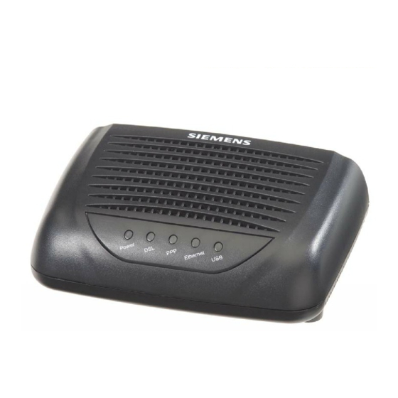
Chapter 1: Overview This chapter provides you the description for the LED and connector for front and rear view of the router. Before you use/install this router, please take a look at this information first. Physical Outlook Front Panel The following illustrations show the front panel of the ADSL Router (with USB interface and without USB interface): LED Indicators The ADSL Router is equipped with five LEDs on the front panel as described in the table below... -
Page 10: Rear Panel
Rear Panel The following figures illustrate the rear panel of your ADSL Router. 9 VAC Connector Description 9 VAC Power connector 9VAC Power switch Ethernet RJ-45 connector Ethernet USB connector (for the model with USB interface only) RJ-11 connector... -
Page 11: Installation
Chapter 2: System Requirement and System Requirement To access the ADSL Router via Ethernet, the host computer must meet the following requirements: The ADSL Router is configured with the default IP address of 192.168.1.1 and subnet mask of 255.255.255.0. As the DHCP server is Enable by default, The DHCP clients should be able to access the ADSL Router. -
Page 12: Connecting The Adsl Router
Connecting the ADSL Router Follow the steps below to connect the related devices. Connecting the ADSL line. Connect the DSL port of the device to your ADSL wall outlet with RJ-11 cable. Please attach one end of the Ethernet cable with RJ-45 connector to the LAN port of your ADSL Router. -
Page 13: Install The Usb Driver
For connecting through a hub, please refer to the following diagram for an example. 9 VAC Install the USB Driver For Windows ME Run the USB installation program from the CD provided by your device package. An InstallShield Wizard will appear. Please wait for a moment. When the welcome screen appears, click Next for next step. - Page 14 An InstallShield Wizard will appear. Please wait for a moment. When the welcome screen appears, click Next for next step. When the InstallShield Wizard Complete appears, click Finish. Plug the USB cable between your device and PC.
-
Page 15: For Windows Xp
Note: If the USB device is not detected, check the USB cable between the PC and the device. Also verify that the device is power on. The system will detect the USB driver automatically. Now, the system will copy the proper files for this device. - Page 16 When the welcome screen appears, click Next for next step. When the InstallShield Wizard Complete appears, click Finish. Plug the USB cable between your device and PC. Note: If the USB device is not detected, check the USB cable between the PC and the device. Also verify that the device is power on.
-
Page 17: For Windows Vista
The system is trying to find proper driver for your device and copying the files automatically. After the file copying is finished, a completing message will appear. You can use the device now. For Windows Vista For Vista users, please press Continue whenever a prompted window asking for permission to continue during USB driver installation process (see the figure below for example). - Page 18 When the welcome screen appears, click Next for the next step. When the complete message of InstallShield Wizard appears, click Finish. Link your router and the PC with a USB cable. The system will detect the USB driver automatically.
- Page 19 Chapter 3: Configuration Note: If the USB device is not detected, check the USB cable between the PC and the device. Also make sure that the device is power on. After the file copying finished, a completing message will appear. You can use the router now.
- Page 20 Copy the USB driver folder from the driver CD to somewhere on the PC. (In our example, the driver files are put under D:\Siemens WHQLed.) Open Start menu, key in cmd in the blank and press enter. Then click cmd.
- Page 21 Method Three – If the USB driver has not been installed yet, you can also connect the router to the PC with a USB cable and wait for Universal Plug and Play device to detect the router, and then install the driver. Plug the USB cable into the USB port on the PC.
- Page 22 Or if you do not have a disc, but have the driver files on your PC, you can follow the steps below: Press I don’t have the disc. Show me other options. Select Browse my computer for driver software (advanced). Press Browse to set the path for the driver file, and then press Next.
- Page 23 Chapter 3: Configuration Now the driver software is installed successfully. Press Close to start using the router. To make sure the USB driver for your router is properly installed, please do the following steps. 1. Open the Start menu and press Control Panel. 2.
- Page 24 3. Press System. 4. Click Device Manager. 5. Confirm that the Siemens ADSL Router USB Remote NDIS Device (BCM63xx Based) is...
-
Page 25: Uninstall The Usb Driver
For Windows ME For uninstall the USB driver, please do the following. The first way: Choose Programs – Siemens Broadband – Uninstall Siemens ADSL Router USB Driver from the Start menu. The InstallShield Wizard dialog will appear. A dialog appears to ask you confirm if you want to remove the USB driver or not. Please click Ok. -
Page 26: For Windows 2000
For uninstall the USB driver, there are two ways to do it. Please do as the following: The first way: Choose Programs – Siemens Broadband – Uninstall Siemens ADSL Router USB Driver from the Start menu. The InstallShield Wizard dialog will appear. - Page 27 Chapter 3: Configuration When the Unsafe Removal of Device screen appears, the USB driver is removed successfully. Click OK. When the Maintenance Complete screen appears, the USB driver is removed successfully. Click Finish.
- Page 28 The second way: Choose Settings –Control Panel from the Start menu. Choose Add/Remove Programs. A dialog appears to ask you choose the program that you want to remove. Please select Siemens ADSL Router USB Driver and click Change/Remove.
- Page 29 Chapter 3: Configuration The InstallShield Wizard dialog will appear. A dialog appears to ask you confirm if you want to remove the USB driver or not. Please click Ok. Unplug the USB cable between your device and your PC. Then click OK.
-
Page 30: For Windows Xp
Click Finish. For Windows XP For uninstall the USB driver, there are two ways to do it. Please do as the following: The first way: Choose Programs – Siemens Broadband – Uninstall Siemens ADSL Router USB Driver from the Start menu. - Page 31 Chapter 3: Configuration The InstallShield Wizard dialog will appear. A dialog appears to ask you confirm if you want to remove the USB driver or not. Please click Ok. Unplug the USB cable between your device and your PC. When the Unsafe Removal of Device screen appears, the USB driver is removed successfully.
- Page 32 The second way: Choose Settings –Control Panel from the Start menu. Choose Add/Remove Programs. A dialog appears to ask you choose the program that you want to remove. Please select Siemens ADSL Router USB Driver and click Change/Remove.
- Page 33 The InstallShield Wizard dialog will appear. Unplug the USB cable between your device and your PC. Then click OK. When the Maintenance Complete screen appears, the USB driver is removed successfully. Click Finish. For Windows Vista For Vista users, please press Continue whenever a prompted window asking for permission to continue during USB driver uninstallation process (see the figure below for example).
- Page 34 To uninstall the USB driver, there are two ways to do it. Please follow the instructions. Method One: Remove from Device Manager. Choose Start menu, and then select Control Panel. Click System and Maintenance. Press System.
- Page 35 Chapter 3: Configuration Click Device Manager. Right click Askey ADSL Router USB Remote NDIS Device on the Network adapters list, and press Uninstall. Click OK when the Confirm Uninstall window appears.
- Page 36 Remember to unplug the USB cable before continue the uninstallation, or you will see the reminder as follows. Unplug and press OK. When the Confirm Device Uninstall screen show up, check Delete the driver software for the device and click OK to continue. Wait while the system is uninstalling.
- Page 37 Note: If your USB driver is installed by UPnP device, you can only use method one (via the Device Manager) to uninstall, because the installed driver will not be shown on the program list. Unplug your USB cable between your router and your PC. Choose Start menu, and open Control Panel folder.
-
Page 38: Setting Tcp/Ip
The USB driver is successfully removed now. Setting TCP/IP In order to access the Internet through the router, each host on your network must install/setup TCP/IP. Please follow the steps below for select a network adapter. -
Page 39: For Windows 98
For Windows 98 Click on the Start menu, point to Settings and click on Control Panel. Double-click the Network icon The Network window appears. On the Configuration tab, check out the list of installed network components. Option 1: If you have no TCP/IP protocol, click Add. - Page 40 On the left side of the windows, highlight Microsoft and then select TCP/IP on the right side. Then click OK When returning to Network window, highlight TCP/IP protocol for your NIC and click Properties. On IP Address tab: Enable Specify an IP address option. Enter the IP Address: 192.168.1.x (x is between 2 and 254) and Subnet Mask: 255.255.255.0 as in figure below.
- Page 41 When returning to Network window, click OK Wait for Windows copying files. When prompted with System Settings Change dialog box, click Yes to restart your computer.
-
Page 42: For Windows Me
For Windows ME 1. Click on the Start menu, point to Settings and click on Control Panel. 2. Double-click the Network icon. 3. The Network window appears. On the Configuration tab, check out the list of installed network components. Option 1: If you have no TCP/IP protocol, click Add. -
Page 43: For Windows Nt
9. Wait for Windows copying files. 10. When prompted with the System Settings Change dialog box, click Yes to restart your computer. For Windows NT 1. Click Start, point to Settings, and then click Control Panel. 2. Double-click the Network icon. 3. - Page 44 5. Click Yes to use DHCP. 6. Insert the Windows NT CD into your CD-ROM drive and type the location of the CD. Then click Continue. 7. Returning to the Network window, you will find the TCP/IP Protocol among the list. Select TCP/IP Protocol and click Properties.
- Page 45 When returning to Network window, click Close. When prompted with Network Settings Change dialog box, click Yes to restart your computer.
- Page 46 For Windows 2000 From the Start menu, point to Settings and then click Network and Dial-up Connections. Right-click the Local Area Connection icon and then click Properties. On the General tab, check out the list of installed network components. Option 1: If you have no TCP/IP Protocol, click Install.
- Page 47 Highlight Protocol and then click Add. Click Internet Protocol (TCP/IP) and then click OK. When returning to Local Area Connection Properties window, highlight Internet Protocol (TCP/IP) and then click Properties. Under the General tab, enable Use the following IP Address. Enter the IP address: 192.168.1.x (x is between 2 and 254), Subnet Mask: 255.255.255.0 and Default gateway:...
- Page 48 For Windows XP From the Start menu, point to Control Panel and then click Network and Internet Connections. Click Network Connection and then click Properties. Click Network Connection and then click Properties.3.On the General tab, check out the list of installed network components.
- Page 49 For Windows Vista Open the Start menu, point to Control Panel and click Click Network and Internet. Select Network and Sharing Center.
- Page 50 Click Manage Network Connection on the left side. Right click Local Area Connection and select Properties. On the Networking tab, you will find Internet Protocol Version 6 and Version 4. Contact your ISP to confirm which one will be used. (We take TCP/IPv4 for example here.) Select Internet Protocol...
-
Page 51: Configure Pc To Get Ip Address From Dhcp
Under the General tab, enable Use the following IP address. Enter the IP address: 192.168.1.x (x is between 2 and 254), Subnet Mask: 255.255.255.0 and Default gateway: 192.168.1.1. Then click Ok.exit. Configure PC to get IP address from DHCP If your ADSL Router operates as a DHCP server for the client PCs on the LAN, you should configure the client PCs to obtain a dynamic IP address. - Page 52 On the IP Address tab, select Obtain an IP address automatically. Then click OK. For Windows NT On the IP Address tab, click on the drop-down arrow of Adapter to select required adapter. Enable Obtain an IP address from a DHCP server and then click OK..
- Page 53 Chapter 3: Configuration For Windows 2000 Enable Obtain an IP address automatically and then click OK.
-
Page 54: Windows Vista
For Windows XP On the IP Address tab, select Obtain an IP address automatically. Then click OK. Windows Vista On the IP Address tab, select Obtain an IP address automatically. Then click OK. -
Page 55: Renew Ip Address On Client Pc
Renew IP Address on Client PC There is a chance that your PC does not renew its IP address after the ADSL Router is on line and the PC cannot access the Internet. Please follow the procedures below to renew PC’s IP address. For Windows 98ME 1. - Page 56 For Windows NT 1. Select Run from the Start menu. 2. Select Run from the Start menu. 3. Type cmd in the dialog box and the click 4. Type ipconfig at prompt. Then you will see the IP information from DHCP server.
- Page 57 For Windows 2000 1. From the Start menu, point to Programs, Accessories and then click Command Prompt. 2. Type ipconfig at prompt. Then you will see the IP information from DHCP server. 3. If you want to get a new IP address, type ipconfig /release to release the previous IP address and then type ipconfig /renew to get a new one.
- Page 58 For Windows Vista 1. Open the Start menu, and type cmd in the text box then click OK. 2. The command prompt window will appear. 3. Type ipconfig at the command window and press Enter to view the computer’s IP information from DHCP server.
- Page 59 Chapter 3: Configuration Note: If you cannot release the IP address successfully and see the message “The requested operation requires elevation,” please go to the Start menu and right click Command Prompt, then set Run as administrator. Press Continue when a dialog asking for permission to continue prompts.
-
Page 60: Chapter 3: Connecting And Accessing
Chapter 3: Connecting and Accessing Prior to configuring the ADSL Router, you must decide whether to configure the ADSL Router as a bridge or as a router. This chapter presents some deployment examples for your reference. Each mode includes its general configure procedures. For more detailed information about web configuration, refer to "Web Configuration". -
Page 61: Ppp Over Atm (Pppoa) Mode
PPP over ATM (PPPoA) Mode STM-1 (Internet Service Provider) BRAS RDAIUS Server *BRAS: Broadband Remote Access Server Description: In this deployment environment, the PPPoA session is between the ADSL WAN interface and BRAS. The ADSL Router gets a public IP address from BRAS when connecting to DSLAM. The multiple client PCs will get private IP address from the DHCP server enabled on private LAN. -
Page 62: Ppp Over Atm (Pppoa) Ip Extension Mode
PPP over ATM (PPPoA) IP Extension Mode STM-1 (Internet Service Provider) BRAS RDAIUS Server *BRAS: Broadband Remote Access Server Description: In this deployment environment, the PPPoA session is between the ADSL WAN interface and BRAS. The ADSL Router acts as a bridge and gets a public IP address from BRAS for your computer. And only the one that got the public IP address is allowed to access into Internet. -
Page 63: Ppp Over Ethernet (Pppoe) Mode
PPP over Ethernet (PPPoE) Mode STM-1 (Internet Service Provider) BRAS RDAIUS Server PPP over Ethernet *BRAS: Broadband Remote Access Server PPPoE+NAT+DHCP on Private LAN Description: In this deployment environment, the PPPoE session is between the ADSL WAN interface and BRAS. The ADSL Router gets a public IP address from BRAS when connecting to DSLAM. -
Page 64: Ppp Over Ethernet (Pppoe) Ip Extension Mode
PPP over Ethernet (PPPoE) IP Extension Mode (Internet Service Provider) STM-1 BRAS RDAIUS Server *BRAS: Broadband Remote Access Server Description: In this deployment environment, the PPPoE session is between the ADSL WAN interface and BRAS. The ADSL Router acts as a bridge and gets a public IP address from BRAS for your computer. And only the one that got the public IP address is allowed to access into Internet. -
Page 65: Numbered Ip Over Atm (Ipoa)
Numbered IP over ATM (IPoA) STM-1 (Internet Service Provider) BRAS RDAIUS Server *BRAS: Broadband Remote Access Server Public IP Pre-assigned Description: If you apply for multiple IP addresses from your ISP, you can assign these public IP addresses to the ADSL Router and public server, e.g., Web or FTP server. - Page 66 Check the network information. Make sure the settings match the settings provided by ISP. Click Finish. Set TCP/IP for your computer. Specify an IP Address, subnet mask and set default gateway. eg: IP Address: 10.3.75.51 Subnet Mask: 255.255.255.248 Gateway: 10.3.75.49 Now the router is well configured.
-
Page 67: Numbered Ip Over Atm (Ipoa)+Nat
Numbered IP over ATM (IPoA)+NAT Description: In this deployment environment, we make up a private IP network of 192.168.1.1. NAT function is enabled (on ADSL Router or use another NAT box connected to hub) to support multiple clients to access the Router and some public servers (WWW, FTP). If you apply for multiple IP addresses from your ISP, you can assign these public IP addresses to the ADSL Router and public server, e.g., Web or FTP server. - Page 68 LAN. Primary IP Address: 192.168.1.1 Subnet mask: 255.255.255.0 Start IP Address: 192.168.1.2 End IP Address: 192.168.1.254 Check Configure the second IP Address and Subnet Mask for LAN Interface and type in the second IP address and subnet mask. Then click Next. Secondary IP Address: 10.3.75.49 Subnet mask: 255.255.255.248 Check the network information.
-
Page 69: Unnumbered Ip Over Atm (Ipoa)
Unnumbered IP over ATM (IPoA) STM-1 (Internet Service Provider) BRAS RDAIUS Server *BRAS: Broadband Remote Access Server Public IP Pre-assigned Description: If you apply for multiple IP addresses from your ISP, you can assign these public IP addresses to the ADSL Router and public server, e.g., Web or FTP server. - Page 70 Set TCP/IP for your computer. Specify an IP Address, subnet mask and set default gateway. eg: IP Address: 10.3.75.51 Subnet Mask: 255.255.255.248 Gateway: 10.3.75.49 Now the router is well configured. You can access into Internet.
-
Page 71: Unnumbered Ip Over Atm (Ipoa)+Nat
Unnumbered IP over ATM (IPoA)+NAT Description: If you apply for multiple IP addresses from your ISP, you can assign these public IP addresses to the ADSL Router and public server, e.g., Web or FTP server. Typically the first IP is network address, the second is used as router IP address and the last one is subnet broadcasting. - Page 72 Start IP Address: 192.168.1.2 End IP Address: 192.168.1.254 Check Configure the second IP Address and Subnet Mask for LAN Interface and type in the second IP address and subnet mask. Then click Next. Secondary IP Address: 10.3.75.49 Subnet mask: 255.255.255.248 Check the network information.
-
Page 73: Bridge Mode
Bridge Mode STM-1 (Internet Service Provider) BRAS RDAIUS Server PPP over Ethernet *BRAS: Broadband Remote Access Server Description: In this example, the ADSL Router acts as a bridge which bridging PC IP address from LAN to WAN. PC IP address can be a static public address that is pre-assigned by ISP or a dynamic public address that is assigned by ISP DHCP server, or can be got from PPPoE software. -
Page 74: Chapter 4: Web Configuration
Chapter 4: Web Configuration Some users might want to set specific configuration for the router such as firewall, data transmission rate… and so on. This chapter will provide you advanced information of the web pages for the router for your reference. Using Web-Based Manager Once your host PC is properly configured, please proceed as follows: 1. -
Page 75: Outline Of Web Manager
Outline of Web Manager For configure the web page, please use admin as the username and the password. The main screen will be shown as below. Title: It indicates the title of this management interface. Main Menu: Includes Quick Start, Status, Advanced and Management. Main It is the current workspace of the web management, containing configuration or status Window:... -
Page 76: Quick Start
Quick Start The pages for the Quick Start provide user a quick way to set for the router. If you do not know more about the router, you can use the Quick Start pages to adjust basic settings to make your router activating. - Page 77 Chapter 5:Connection Mode After clicking on the Next button from the VPI/VCI web page, the following screen will appear. Please choose the connection type and encapsulation mode that you want to use and click Next for next page. For example, PPP over Ethernet (PPPoE) in this screen is selected.
-
Page 78: Ppp Over Atm/ Ppp Over Ethernet
PPP over ATM/ PPP over Ethernet If the type you choose is PPP over ATM or PPP over Ethernet, please refer to the following information. According to the ISP’s configuration on the server, you can choose PPPoE and PPPoA modes. If the ISP provides PPPoE service, the connection type selection will be decided as whether the LAN side device is running a PPPoE client or the router is to run the... - Page 79 PPP Username: Type in the username that you got from your ISP. PPP Password: Type in the password that you got from your ISP. Always On: Check this button to make the connection is always active. Dial on Demand: Click this button to make a connection while in demand.
- Page 80 PCs. Start IP Address: Type in the start point IP address. End IP Address: Type in the end point IP address. Leased Time: Type in the duration for the time. The default is 1day. DHCP Server Off: Check this item if DHCP service isn’t needed on the LAN.
-
Page 81: Ip Over Atm
Chapter 5:Connection Mode IP over ATM If the type you have to choose is IP over ATM, please refer to the following information. IPoA is an alternative of LAN emulation. It allows TCP/IP network to access ATM network and uses ATM quality of service’s features. - Page 82 In the Configure LAN side Settings web page, you have to fill in the data requested here. Primary IP Address: Type in the first IP address that you got from your ISP for your LAN connection. Subnet Mask: Type in the subnet mask that you got from your ISP for your LAN connection.
- Page 83 Chapter 5:Connection Mode Now, the system will reboot to activate the new settings that you have done in this section. Please wait for 2 minutes for restarting the router.
- Page 84 Bridging If the type you choose is Bridging, please refer to the following information. The bridging mode can configure your router to send packets received on any port such as ATM PVC or Ethernet with a broadcast MAC address to all other ports. Choose Bridging and click Next.
- Page 85 Chapter 5:Connection Mode Primary IP Address: Type in the IP address that you got from your ISP for LAN interface. Subnet Mask: Type in the subnet mask that you got from your ISP for LAN interface. MTU: It means the maximum size of the packet that transmitted in the network.
- Page 86 Status Overview This page is displaying the current status for the DSL connection. It includes if the lists the LAN IP address, default gateway, DNS servers IP address, firmware version, the period of activating the router, and so on. The system status will be changed according to the settings that you configured in the web pages.
-
Page 87: Adsl Line
Chapter 5:Connection Mode ADSL Line This page shows all information for ADSL. For knowing the quality of the ADSL connection, please click ADSL BER Test button to have advanced information. Click More Information to show more detailed information about ADSL Line Status. -
Page 88: Internet Connection
When the test is over, the result will be shown on the following dialog for your reference. Click Close to close this dialog. Internet Connection This page displays the connection information for your router, such as PVC name, category, protocol, invoking NAT or not, IP address, link status and so on. - Page 89 Chapter 5:Connection Mode This table shows the IP address record for IP-to-Physical translation in your router.
-
Page 90: Local Network - Dhcp Server
Advanced Setup Local Network- IP Address This page is the same as you can see in the Configure LAN side Settings page while running the Quick Setup. It allows you to set IP Address and Subnet Mask values for LAN interface. Primary IP Address: Type in the first IP address that you got from your ISP for your LAN connection. - Page 91 Chapter 5:Connection Mode DHCP Server On: Check this item if DHCP service is needed on the LAN. The router will assign IP address, gateway address for each of your PCs. Start IP Address: Type in the start point IP address. End IP Address: Type in the end point IP address.
- Page 92 The new one will be shown on the dialog right away. That is, the specified address will be reserved and not be assigned by DHCP for other computer.
-
Page 93: Local Network - Upnp
Chapter 5:Connection Mode Local Network – UPnP The UPnP is available only for Windows XP. If you are not user of Windows XP, this page does not have any meaning to you. This page allows you to enable the UPnP function through the web page for your router. - Page 94 If you choose Non Realtime VBR, you have to type in the following data. The range for Peak Cell Rate is from 1 to 1690. The range for Sustainable Cell Rate is from 1 to 1689 and must be smaller than Peak Cell Rate.
-
Page 95: Internet-Dns Server
Internet-DNS Server If Enable Automatic Assigned DNS checkbox is selected, this router will accept the first received DNS assignment from one of the PPPoA, PPPoE or MER/DHCP enabled PVC(s) during the connection establishment. If the checkbox is not selected, it is necessary for you to enter the primary and optional secondary DNS server IP addresses. -
Page 96: Internet - Adsl Settings
Internet - ADSL Settings Enable ADSL Port: Check this box to enable this function. It simply invokes the line mode that you choose here for the router. Select the support of line modes: There are several selections for your choosing. Select the one that you need. For Example, if you want to change one or more physical layer parameters while the ATU-x is in data transfer state, and the transmission... -
Page 97: Configuring Other Routers On Your Lan
Allow you to remove the selected static route settings. Adding a New One To add a static route, please choose Static Route - Add. Type the destination network address, subnet mask and gateway that you get from ISP and click Apply. Destination Network Address: The destination IP address of the network where data packets are to be sent. -
Page 98: Ip Routing - Dynamic Routing
For a router with a direct connection to the Router’s local Router, the Gateway IP Address is the address of the Router’s local router. For routers which must forward packets to another router before reaching the Router’s local router, the Gateway IP Address is the address of the intermediate router. Example –... - Page 99 Chapter 5:Connection Mode different interface. Otherwise, disable this function. Click Apply to invoke the settings set here.
-
Page 100: Virtual Server-Port Forwarding
Virtual Server-Port Forwarding The Router implements NAT to let your entire local network appear as a single machine to the Internet. The typical situation is that you have local servers for different services and you want to make them publicly accessible. With NAT applied, it will translate the internal IP addresses of these servers to a single IP address that is unique on the Internet. -
Page 101: Ip Address Seen By Internet Users
Chapter 5:Connection Mode IP Address seen by Internet Users Please note that, in the above picture, both Internet users are connecting to the same IP address, but using different protocols. To Internet users, all virtual servers on your LAN have the same IP Address. This IP Address is allocated by your ISP. -
Page 102: Connecting To The Virtual Servers
From Internet Host IP Address: Select the initial place for port forwarding. If you choose SINGLE, a box will appear for you to fill in the IP address for the specific host. And, if you choose SUBNET, the boxes of IP and Subnet will appear for you to fill in the IP address and subnet mask for the specific host as the start point. -
Page 103: Virtual Server - Dmz Host
Or define by yourself by typing the words into the field of User defined. Click Apply to complete the setting. Virtual Server - DMZ Host Direct Mapping Zone (DMZ) uses a technology that makes Router forwarding all incoming packet to internal specific server. To close the function of DMZ Host, please click Discarded. -
Page 104: Virtual Server - Dynamic Dns
Virtual Server - Dynamic DNS The Dynamic DNS (Dynamic Domain Nasme System) combines both functions of DNS and DHCP to map a dynamic IP into a fixed domain name. This page allows you to access into virtual servers with a domain name and password. Dynamic DNS:... - Page 105 Firewall The firewall is a software that interrupts the data between the Internet and your computer. It is the TCP/IP equivalent of a security gate at the entrance to your company. All data must pass through it, and the firewall (functions as a security guard) will allow only authorized data to be passed into the LAN.
- Page 106 Then, to add a new IP Filtering, click Add. This page provides some settings for you to adjust for adding a new outbound IP Filtering. Allow Traffic: No stops the data transmission, Yes lets the data pass through. Protocol: Here provide several default policies for security levels for you to choose.
-
Page 107: Quality Of Service
Chapter 5:Connection Mode A new IP filtering setting for Outbound traffic is created in the web page. To edit the setting, please click the pencil mark to get into the editing page. To delete the setting, click the trash mark to erase it. To set another IP filtering, click Add again. - Page 108 is the default setting. IP type of Service: The system provides some types of service for you to choose. The meaning of each type is the same as the denotation. The default one is No change. IPQoS To classify the upstream traffic by assigning the transmission priority of the data for different users, please use IP QoS to prioritize the data transmission.
-
Page 109: Port Mapping
Chapter 5:Connection Mode you want to invoke the QoS traffic rule. Destination Port: Type in the destination port for the traffic rule. The range is from 0 to 65535. Traffic Priority: There are three options – Low, Medium, and High that you can choose. It decides the order of each data transmitted through this device. - Page 110 Group Name: Type in a name here as a group name. It must be unique. The word length must not be over the length of the field. Available Interfaces: The available interfaces (such as Ethernet, USB etc.) will be displayed in the left side box.
- Page 111 Chapter 5:Connection Mode Management Diagnostics To check the link status for the network and your computer, a diagnostic test can guide you to detect the network problem. The testing items are listed and accomplished one by one. If the previous one is failed, than the items below that failed one will be failed too.
-
Page 112: Admin Account
Admin Account This page allows you to type in the password for accessing into your DSL Router. For the Admin Account, the default setting for user password is admin. If you want to change the username and the password, please retype the new password in the Confirm field for confirmation. -
Page 113: Interntet Time
Chapter 5:Connection Mode Interntet Time The router’s clock must synchronize with global Internet’s time. The time you set in the screen will be adapted to system log. Update: Click this button to refresh the current time. Set Time by: The default setting is Manual. If you select Time Server, you don’t need to type in the time setting manually. -
Page 114: Viewing System Log
There are 8 types for log level and display level for your choose. The default is Debugging. The mode selection includes Local, Remote and Both. The default one is Local. If you choose Remote or Both, all the events will be sent to the specified UDP port of the specified log server. -
Page 115: Snmp Setting
Chapter 5:Connection Mode SNMP Setting The SNMP, the abbreviation of Simple Network Management Protocol, is used to refer to a collection of specifications for network management that include the protocol itself, the definition of data structures and associated concepts. A management station performs the monitoring function by retrieving the value of MIB objects. The management station and agents are linked by a network management protocol that is SNMP. -
Page 116: Backup Config
workstation by way of SNMP agent. Backup Config To backup your configuration for the router to your computer, you can use Backup Config web page to save the settings. And when you want to restore the settings in the future, simply open Backup Config web page and use Browse button to locate the file and click Restore. -
Page 117: Upnp For Xp
UPnP for XP Universal plug and play (UPnP) is an architecture for pervasive peer to peer network connectivity of intelligent appliances and PCs of all form factors. It is designed to bring easy-to-use, flexible, standards-based connectivity to ad-hoc or unmanaged networks whether in the home, in a small business, public spaces, or attached to the Internet. - Page 118 7. Now, the NAT traversal function will be provided. The ADSL router will create a new virtual server automatically for mapping while the router detecting the computer running some Internet applications.
-
Page 119: Chapter 5: Troubleshooting
Chapter 5: Troubleshooting If the suggested solutions in this section do not resolve your issue, contact your system administrator or Internet service provider. Problems with LAN PCs on the LAN cannot get IP addresses from the ADSL Router. The chances are that the interface used as DHCP server is modified and the client PCs do not renew IP addresses. -
Page 120: Problems With Upgrading
Request time out Then the DNS is not reachable. Check your DNS setting on the ADSL Router. Problems with Upgrading The following lists the error messages that you may see during upgrading and the action to take. Error: All the ADSL LEDs light up and cannot light off as usual. Possible cause: When users execute firmware upgrade and save settings to the router, the power for the router is lost for some unknown reasons, the normal web page for the router might be damaged. -
Page 121: Chapter 6: Glossary
ARP (Address Resolution Protocol ) ARP is a TCP/IP protocol for mapping an IP address to a physical machine address that is recognized in the local network, such as an Ethernet address. A host wishing to obtain a physical address broadcasts an ARP request onto the TCP/IP network. -
Page 122: Private Ip Address
configured and mapped to a private workstation address when accesses are made through the gateway to a public network. For example, the ADSL Router is assigned with the public IP address of 168.111.2.1. With NAT enabled, it creates a Virtual LAN. Each PC on the Virtual LAN is assigned with a private IP address with default value of 192.168.1.2 to 192.168.2.254. - Page 123 Chapter 7: Glossary the cells belonging to the same connection can be distinguished. A unique and separate VPI/VCI identifier is assigned in advance to indicate which type of cell is following, unassigned cells, physical layer OAM cells, metasignaling channel or a generic broadcast signaling channel.
-
Page 125: Appendix A: Specifications
Appendix A: Specifications Interface One RJ-11 port for ADSL connection Four RJ-45 ports for IEEE 802.3/802.3u 10/100 Base-T auto-sensing and auto-crossover Ethernet connection One USB client port compliant to USB 1.1 One hidden reset button for restoring to factory default settings Regulatory EMI: FCC part 15 Class B, CE... -
Page 127: Appendix B: Server Setup For 802.1X Client
Appendix B: Server Setup for Getting Client Certificate Please connect the client to a network that doesn’t require port authentictaion. Open up Microsoft Explorer in Windows XP, and go to http://<yourserver>/certsrv. Authenticate to the server using your account that you created at the end of the server setup. - Page 128 Make sure that User certificate request: User Certificate is selected, and click Next. Click Submit in this dialog. Now, you'll see status messages on the screen, then your certificate will be returned to you. Click Install this certificate. You'll receive a confirmation message about accepting the certificate, click...
-
Page 129: Appendix C: Weee - B2C
For more detailed information about disposal of your old appliance, please contact your city office, waste disposal service, the shop where you purchased the product or your SIEMENS partner. The statements quoted above are only fully valid for equipment which is installed in the countries of the European Union and is covered by the directive 2002/96/EC.