
Related Manuals for Shure The SM58 Vocal Artist UHF


Summary of Contents for Shure The SM58 Vocal Artist UHF
- Page 1 Model UHF-R Wireless User Guide Model UHF-R Wireless User Guide ..... 5 Printed in U.S.A. 2006, Shure Incorporated © 27NS8849C (Rev. 1)
-
Page 2: Important Safety Instructions
READ these instructions. KEEP these instructions. HEED all warnings. FOLLOW all instructions. DO NOT use this apparatus near water. CLEAN ONLY with dry cloth. DO NOT block any ventilation openings. Install in accordance with the manu- facturer's instructions. DO NOT install near any heat sources such as radiators, heat registers, stoves, or other apparatus (including amplifiers) that produce heat. -
Page 3: Table Of Contents
English Contents Important Safety Instructions ..........3 Feature Overview . -
Page 4: Feature Overview
The system’s band and frequency range are identified on the face of the receiver and transmitter. For example, “H4 518–578 MHz.” For information on bands available in your area, consult your local dealer or phone Shure. More information is also available at Shure’s website (www.shure.com). -
Page 5: System Components
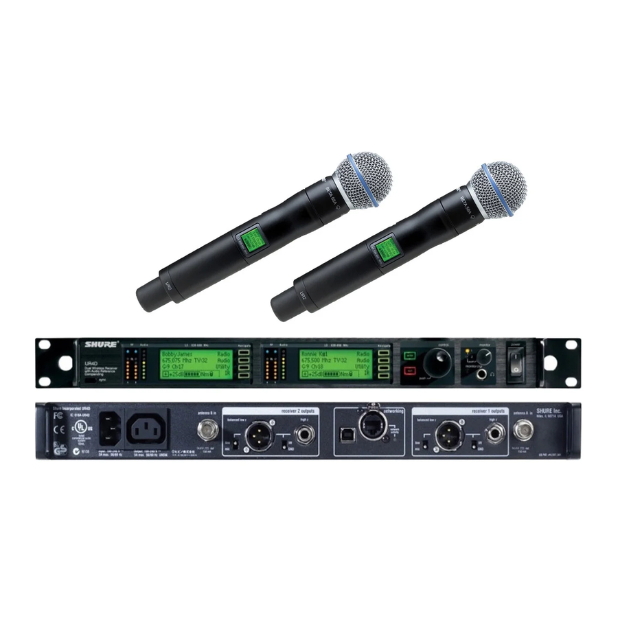
English System Components All systems include: Two Antenna Cables Shure’s Wireless Workbench Software UR4S or UR4D Receiver (UR4D pictured) Two 1/2 Wave Antennas IEC Power Cable Transmitter Carrying Case 2 Antenna hole plugs 4 Rack Mount Screws with Washers IEC Power Extension Cable AA Batteries Ethernet Network Cable with “Ruggedized”... -
Page 6: Receiver Controls And Connectors
Shure UHF-R Wireless Receiver Controls and Connectors UR4S Wireless Receiver with Audio Reference Conpanding sync ³ SYNC Infrared (IR) port. Transmits group, channel, and other settings to a transmitter. See page 15. · Squelch LEDs. • Blue (On) = Transmitter signal detected •... -
Page 7: Receiver Lcd Interface
Receiver LCD Interface Menu Access Press the Navigate key next to the menu item you want to select. Radio SHURE Audio 524-025 MHz TV: 32 Util G: 3 Ch: 1 Out: -0dB Sync +12 dB F, P, FP Transmitter Status Display Everything under the dotted line reflects the settings for the transmitter, if present. - Page 8 Shure UHF-R Wireless Network Parameters NOTE: • The receiver reboots after you press ENTER to accept net- work parameter changes • In dual models (UR4D), these settings affect both receivers (the dual receiver is treated as a single network device).
-
Page 9: Automatic Frequency Selection
Automatic Frequency Selection Follow these steps to use the channel scan and group scan features. Before you begin... • Install the receivers in the location where they will be used and power them on. • Mute all inputs on mixing devices connected to receivers. •... -
Page 10: Networking Receivers
NOTE: Dual receivers use a single IP address, which may be set through either LCD interface. Existing UHF Network Installations Both Shure’s UHF-R receivers and legacy UHF receivers can be networked to the same PC and accessed using the latest Wireless Workbench software. -
Page 11: Handheld And Bodypack Transmitter Controls And Connectors
Handheld and Bodypack Transmitter Controls and Connectors ³ Interchangeable microphone head (BETA 87A pictured). · LCD Panel. » Power Switch. ¿ Control buttons for LCD interface. ´ Infrared (IR) port. See page 15. ² Battery compartment. Transmitter LCD Interface exit Key. Move to the left, or exit 779.475MHz Main Menu Transmitter Batteries... -
Page 12: Transmitter Parameters
Shure UHF-R Wireless Transmitter Parameters Press ENTER from the main menu to access the following parameters: G:34 Ch:21 779.475MHZ Gain +20dB SHURE INC. Use the following key combinations to access additional features and parameters: hold LCD Panel Changes LCD Panel... -
Page 13: Automatic Transmitter Sync
Automatic Transmitter Sync This feature automatically updates a bodypack or handheld transmitter’s group and channel settings to match those of a selected receiver. To perform a transmitter sync... 1. Open the transmitter battery cover to display the infrared (IR) port. 2. -
Page 14: Troubleshooting
Shure UHF-R Wireless Troubleshooting Issue No sound Faint Sound or Distortion Lack of range, unwanted noise bursts, or drop outs Cannot turn transmitter off or change frequency settings, or can’t program receiver Excessive hum or buzzing Power Make sure that the transmitter and receiver are receiving sufficient voltage. -
Page 15: Specifications
Specifications Frequency Range and Transmitter Output Power Band Range Transmitter power (mW) Handheld H4E, 518-578 MHz 10 / 50 10 / 50 J5E, 578-638 MHz 10 / 50 (578-608, 614-638) 10 / 50 L3E, 638-698 MHz 10 / 50 10 / 50 740-814 MHz 10 / 50 790-865... -
Page 16: Inputs And Outputs
Shure UHF-R Wireless Inputs and Outputs UR1 Transmitter Audio Input Connector: 4-Pin male mini connector (TA4M) Input Configuration: Unbalanced, active Actual Impedance: >1 M Maximum Input Level: +10 dBu (sensitivity 0 dB) +20 dBu (sensitivity –10 dB) 1 kHz, 1% THD... -
Page 17: Replacement Parts And Accessories
Networking Interface connector for computer control and monitoring. The receiver shall have a volume control and an adjustable noise squelch control. The system shall be the Shure UHF-R Wireless. Antenna Combiners and Accessories •... - Page 18 Licensing: A ministerial license to operate this equipment may be required in certain areas. Consult your national authority for possible requirements. Changes or modifications not expressly approved by Shure Incorporated could void your authority to operate the equipment. Licensing of Shure wireless microphone equipment is the user's responsibility, and licensability depends on the user's classification and application, and on the selected frequency.
- Page 19 SYSTEM COMPATIBILITY GUIDE FOR FREQUENCY BANDS H4, H4E, J5, J5E, L3, L3E, Q5, Q9, R9, A24, JBX, Q6 AND Q10 SYSTÈMES COMPATIBLES EN FRéQUENCE DANS LA BANDES H4, H4E, J5, J5E, L3, L3E, Q5, Q9. R9, A24, JBX, Q6 ET Q10 FREQUENZKOMPATIBLE SYSTEME IM FREQUENZBEREICH H4, H4E, J5, J5E, L3, L3E, Q5, Q9.
- Page 20 J5 FREQUENCY BAND (578.000 - 607.975 - 614.025 - 638.000 MHz) 32 & 37 33 & 38 Channel Group 1 Group 2 578.350 584.350 578.850 584.850 579.575 585.575 580.500 586.500 581.625 587.625 582.450 588.450 583.075 589.075 583.475 589.475 614.125 614.650 615.675 617.025 617.750...
- Page 21 42 & 47 43 & 48 Channel Group 1 Group 2 Group 3 638.350 644.350 650.350 638.850 644.850 650.850 639.575 645.575 651.575 640.500 646.500 652.500 641.625 647.625 653.625 642.450 648.450 654.450 643.075 649.075 655.075 643.475 649.475 655.475 668.125 674.125 680.125 668.650 674.650 680.650...
- Page 22 59 & 64 60 & 65 Channel Group 1 Group 2 746.350 740.350 746.850 740.850 747.575 741.575 748.500 742.500 749.625 743.625 750.450 744.450 751.075 745.075 751.475 745.475 776.125 770.125 776.650 770.650 777.675 771.675 779.025 773.025 779.750 773.750 780.150 774.150 780.975 774.975 781.600 775.600...
- Page 23 Full Range Full Range max. # of max. # of comp. fre- comp. fre- User Group quencies quencies (option 1) (option 2) Channel Group 1 Group 2 518.100 518.900 518.825 519.625 519.350 520.150 520.375 521.175 521.725 522.525 522.350 523.150 525.150 525.950 530.250 531.050...
- Page 24 J5E FREQUENCY BAND (578.000 - 638.000 MHz) (Continued) Channel Group 1 Group 2 630.200 627.175 631.175 628.650 632.375 631.325 632.875 633.375 635.825 634.250 636.900 636.600 637.625 637.625 581.200 581.775 586.450 592.150 592.725 594.275 597.900 595.825 598.600 598.850 604.000 600.400 605.350 601.550 614.450 610.650...
- Page 25 Full Range Full Range Full Range max. # of max. # of comp. fre- comp. fre- comp. fre- quencies quencies (option 1) (option 2) Channel Group 1 Group 2 740.300 740.425 740.825 740.850 742.400 742.100 742.800 742.650 745.000 744.025 745.975 744.675 748.850 745.600...
- Page 26 783.000 784.975 797.500 786.775 797.900 797.900 799.000 800.225 805.100 804.000 806.300 805.100 808.225 807.000 808.975 808.225 810.775 812.700 813.100 813.500 746.775 744.225 749.100 748.700 752.225 749.100 754.775 752.225 756.700 754.775 764.000 764.000 782.300 768.225 784.225 772.000 784.975 780.700 788.000 791.000 792.225 794.025 813.900...
- Page 27 Full Range Full Range Full Range max. # of max. # of max. # of compatible compatible compatible frequencies frequencies frequencies (option 1) (option 2) (option 3) Channel Group 1 Group 2 Group 3 790.650 791.300 790.725 791.900 792.050 791.825 794.200 793.225 792.500...
- Page 28 Germany Germany Germany preferred: preferred: preferred: User Group User Group User Group 3D 790-814 2 790-814 1 790-814 MHz & MHz & MHz & 838-865 838-862 838-862 Group 12 Group 13 Group 14 Channel 790.400 790.100 791.050 791.350 793.325 792.175 794.975 794.425 792.750...
- Page 29 BEL / TUR / Optimized: U.K. TV Ch. 67- preferred: preferred: 69 & EU “Ch. 69 Co- TV Ch. 69 & harmonized ordinate 838-862 & frequencies harmonized 863-865 SET 1" 854-862 & 863-865 Group 33 Group 34 Group 35 Channel 854.225 838.650 855.675...
- Page 30 Channel 779.125 779.375 780.125 780.750 782.000 782.500 797.125 797.375 798.125 798.750 800.000 800.500 Channel 783.625 783.875 784.625 785.250 786.500 801.625 801.875 802.625 803.250 804.500 805.000 Channel 779.125 779.500 779.375 779.875 780.875 782.375 781.875 784.125 783.750 786.500 786.125 787.500 787.250 787.750 Channel 797.125 797.375...
- Page 31 Channel Group 1 Group 2 806.125 806.250 806.375 806.500 807.125 807.000 807.750 807.875 809.000 808.500 809.500 808.875 Channel 806.250 807.625 806.750 808.750 809.500 809.375 809.750 809.750 Q6 FREQUENCY BAND (740.125 - 751.875 MHz) Channel Group 1 Group 2 740.275 740.275 741.000 740.825 741.450...
- Page 32 Works with Works with UA G1 UA G2 Channel Group 1 Group 2 740.450 740.600 741.425 742.500 743.075 743.000 745.350 744.050 746.050 744.700 747.350 746.700 748.150 749.000 751.875 752.125 753.625 754.650 756.050 756.100 757.150 757.900 763.525 760.925 764.950 768.675 749.725 741.700 752.350 746.150...
- Page 33 EN60065 EN61000-3-2:2000 Amendment A1:1998; A2:1998; A14:2000 EN 61000-3-3 Amendment A1:2001 The technical documentation is kept at: Shure Incorporated, Corporate Quality Engineering Division SHURE Europe GmbH, EMEA Approval Manufacturer: Shure Incorporated Signed: __________________________________ Date: 6 January 2005 Name and Title: Craig Kozokar, EMC Project Engineer, Corporate Quality Engineering Division...
- Page 34 United States, Canada, Latin America, Caribbean: 5800 W. Touhy Avenue, Niles, IL 60714-4608, U.S.A. Phone: 847-600-2000 U.S. Fax: 847-600-1212 Intl Fax: 847-600-6446 Europe, Middle East, Africa: Shure Europe GmbH, Phone: 49-7131-72140 Fax: 49-7131-721414 Asia, Pacific: Shure Asia Limited, Phone: 852-2893-4290 Fax: 852-2893-4055...