
Summary of Contents for Sharper Image SI263
- Page 1 Intelligent Battery Manager SI263 Instructions Read and save these instructions. SI263 IM 0205v1.indd 1 3/2/05 4:41:02 PM...
- Page 2 Enjoy your purchase! Respectfully, Richard Thalheimer Founder, Chairman and Chief Executive Officer Call 1-800-344-4444 for 24-7 ordering and customer service, or go to , our complete online store. SI263 IM 0205v1.indd 2 3/2/05 4:41:06 PM...
-
Page 3: Table Of Contents
Charging Battery in the Vehicle ...14 Negative-Grounded System (Standard) ...16 Positive-Grounded System ...17 Charging a Removed Battery ...18 Operating Features ...20 Charge Rate ...20 Battery Type Button ...21 General Notes ...22 Charging Tips ...23 SI263 IM 0205v1.indd 3 3/2/05 4:41:06 PM... - Page 4 Table of Contents Maintenance and Care ...24 Troubleshooting ...25 Statement of FCC Compliance ...30 FCC Label Compliance Statement ...31 SI263 IM 0205v1.indd 4 3/2/05 4:41:06 PM...
-
Page 5: Important Safety Precautions
Review cautionary markings on these products and on the engine. SAVE THESE INSTRUCTIONS — This manual contains important safety and operating instructions. SI263 IM 0205v1.indd 5 3/2/05 4:41:06 PM... -
Page 6: Warnings
• Always charge batteries in a well-ventilated area. The Battery Manager produces heat during operation and requires proper ventilation. Air-flow is required around the entire unit. SI263 IM 0205v1.indd 6 Warnings 3/2/05 4:41:07 PM... - Page 7 The gases from the battery will corrode and damage the Battery Manager. • Never touch the battery clamps together when the Battery Man- ager is on. This could cause a spark. SI263 IM 0205v1.indd 7 Warnings 3/2/05 4:41:07 PM...
- Page 8 Pulling on the cord may cause damage to the cord or the plug. • Do not operate the Battery Manager if it has a damaged power cord or plug. Replace the cord. SI263 IM 0205v1.indd 8 Warnings 3/2/05 4:41:07 PM...
-
Page 9: Personal Safety Precautions
A battery can produce a short-circuit current high enough to weld a ring (or similar object) to metal, causing a severe burn. SI263 IM 0205v1.indd 9 3/2/05 4:41:07 PM... -
Page 10: Charging Preparation
• Before attempting to clean up a battery, neutralize any acid spills thoroughly with baking soda. Charging Preparation Power The Battery Manager requires a three-prong grounded 120V AC outlet that meets all local codes and ordinances. Grounding Pin SI263 IM 0205v1.indd 10 Grounding Outlet 3/2/05 4:41:07 PM... -
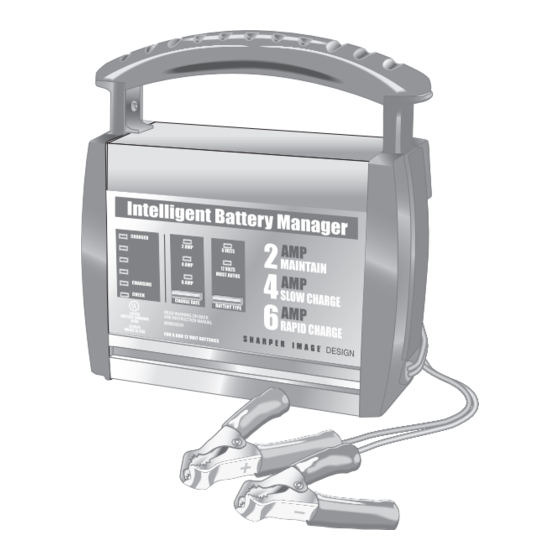
Page 11: Features
• Electronic push-button controls for selecting charge rate and battery type. • Wall-mountable, high-impact, corrosion-resistant molded case. • 2 amp Maintenance Charge. • 4 amp Slow Charge. • 6 amp Rapid Charge. SI263 IM 0205v1.indd 11 Features Features 3/2/05 4:41:07 PM... -
Page 12: Extension Cord Use
• Ensure the wire length and gauge correspond to the AC ampere rating, as specified in the chart below: Extension Cord (Minimum Recommended) Length of Cord (Feet) AWG* Size of Cord *AWG=American Wire Gauge SI263 IM 0205v1.indd 12 Extension Cord Use 3/2/05 4:41:07 PM... -
Page 13: Battery Preparation
This helps purge excessive gases from the cells. Do not overfill. If the battery is sealed, with non-removable vent caps, no action is necessary. SI263 IM 0205v1.indd 13 Battery Preparation 3/2/05 4:41:07 PM... -
Page 14: Operation
1. To avoid personal injury, stand clear of all fan blades, belts, pulleys and other engine parts. 2. To avoid damaging the Battery Manager, keep the power cord and output cords away from the hood, door and moving engine parts. SI263 IM 0205v1.indd 14 Battery Preparation Operation 3/2/05 4:41:07 PM... - Page 15 NEGATIVE (NEG, N or -). The positive post is usually marked red and is larger than the negative post. 4. Identify which battery post is grounded or connected to the chassis. THIS IS NORMALLY THE NEGATIVE POST. SI263 IM 0205v1.indd 15 3/2/05 4:41:08 PM...
-
Page 16: Negative-Grounded System (Standard)
5. To disconnect the Battery Manager, unplug its power cord before disconnecting the output clamps. While standing away from the battery, remove the output clamp from the chassis or engine block. Finally, remove the output clamp from the battery post. SI263 IM 0205v1.indd 16 3/2/05 4:41:08 PM... -
Page 17: Positive-Grounded System
DO NOT connect to the positive battery post, carbu- retor, and fuel line or sheet metal part. POSITIVE BATTERY SI263 IM 0205v1.indd 17 NEGATIVE BATTERY CHARGER POWER CORD 24", 6 GAUGE... -
Page 18: Charging A Removed Battery
4. Position yourself as far away from the battery as possible and connect the NEGATIVE (black) output clamp to the free end of the cable. 5. Plug the power cord into an AC outlet. SI263 IM 0205v1.indd 18 3/2/05 4:41:08 PM... - Page 19 While standing away from the battery, remove the output clamp from the NEGATIVE battery post. Finally, remove the output clamp from the POSITIVE battery post. 8. Clean and store the Battery Manager in a dry location. SI263 IM 0205v1.indd 19 3/2/05 4:41:08 PM...
-
Page 20: Operating Features
Note: The 2A rate is not intended for use as a trickle charge for larger batteries. • 6A CHARGE RATE: For charging automotive and marine batter- ies. Not intended for industrial applications. SI263 IM 0205v1.indd 20 Charge Rate Control Panel 3/2/05 4:41:08 PM... -
Page 21: Battery Type Button
Battery Manager and plug it in again. Charging Complete: The CHARGED (green) LED illuminates when charging is complete. The Battery Manager stops charging and switches automatically to Maintain Mode. SI263 IM 0205v1.indd 21 Battery Type Button 3/2/05 4:41:08 PM... -
Page 22: General Notes
• The Battery Manager is equipped with a relay. This device switches on and off the charge current to the battery. It is normal to hear an occasional clicking sound when the relay switches on or off. SI263 IM 0205v1.indd 22 Battery Type Button General Notes 3/2/05 4:41:08 PM... -
Page 23: Charging Tips
4 yellow LEDs, the Battery Manager may enter Maintain Mode. However, if the original charge was started using the 6A rate, the charge can often be completed using the 2A rate. SI263 IM 0205v1.indd 23 Charging Tips 3/2/05 4:41:08 PM... -
Page 24: Maintenance And Care
Battery Manager. • Clean the case of the Battery Manager with a soft cloth to main- tain its shiny finish and help prevent corrosion. • Store the Battery Manager in a clean, dry location. SI263 IM 0205v1.indd 24 3/2/05 4:41:08 PM... -
Page 25: Troubleshooting
Performance problems can often be corrected by the user. Please review the following chart completely for possible solutions to common problems: PROBLEM The CHECK (red) LED is illuminated. SI263 IM 0205v1.indd 25 Troubleshooting POSSIBLE CAUSE The battery is not connected correctly. The CHARGE RATE... - Page 26 “Operating Fea- tures” section. The CHECK (red) LED is flashing. SI263 IM 0205v1.indd 26 Troubleshooting POSSIBLE CAUSE A button may have been pressed while the Battery Manager was plugged in. The Battery Manager may be defective.
- Page 27 PROBLEM The CHECK (red) LED always flashes before the battery is com- pletely charged. SI263 IM 0205v1.indd 27 Troubleshooting POSSIBLE CAUSE This happens if the battery does not reach full charge within 24 hours. May be due to a very large battery...
- Page 28 The Battery Man- ager is making an audible clicking sound. SI263 IM 0205v1.indd 28 Troubleshooting POSSIBLE CAUSE The battery may be fully charged or recently charged, leaving the battery voltage high enough to appear to be fully charged.
- Page 29 PROBLEM The measured current is much lower than was selected. SI263 IM 0205v1.indd 29 Troubleshooting POSSIBLE CAUSE The Battery Man- ager reached the maximum voltage and is reducing the current. SOLUTION No problem. This is a normal condition. 3/2/05 4:41:09 PM...
-
Page 30: Statement Of Fcc Compliance
If this equipment does cause harmful interference to radio or television reception, which can be determined by turning the equipment off and on, the user is encouraged to try to correct the interference by one or more of the following measures: SI263 IM 0205v1.indd 30 3/2/05 4:41:09 PM... -
Page 31: Fcc Label Compliance Statement
This device complies with Part 15 of the FCC Rules. Operation is subject to the following two conditions: (1) This device may not cause harmful interference, and (2) this device must accept any interference received, including interference that may cause undesired operation. SI263 IM 0205v1.indd 31 3/2/05 4:41:09 PM... - Page 32 650 Davis St., San Francisco, CA 94111 (415) 445-6000 Shop online: Due to continuing improvements, actual product may differ slightly from the product described herein. V1 02/05 SI263 IM 0205v1.indd 32 WARRANTY T.S.I. - Returns Department 2901-A West 60th Street Little Rock, AR 72209...