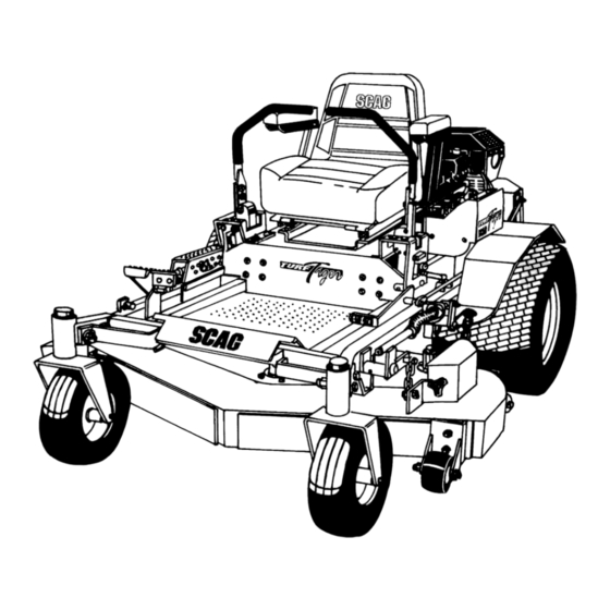
Scag Power Equipment STT Operator's Manual
Scag mower operator's manual
Hide thumbs
Also See for STT:
- Operator's manual (129 pages) ,
- Operator's manual (77 pages) ,
- Operator's manual (76 pages)
Table of Contents
Advertisement
Advertisement
Table of Contents

Related Manuals for Scag Power Equipment STT


Summary of Contents for Scag Power Equipment STT
- Page 1 MODEL STT PART NUMBER 03059...
- Page 2 WARNING: REMEMBER - YOUR MOWER IS ONLY AS SAFE AS THE OPERATOR! Hazard control and accident prevention are dependent upon the awareness, concern, prudence, and proper training of the personnel involved in the operation, transport, maintenance, and storage of the equipment.
-
Page 3: General Information
Section 1 1.1 INTRODUCTION SERIAL NUMBER PLATE LOCATION Figure 1-1 Tractor Serial Number Plate Location GENERAL INFORMATION 1.2 DIRECTION REFERENCE 1.3 SERVICING THE ENGINE AND DRIVE TRAIN COMPONENTS 390S0137... -
Page 4: Safety Information
Section 2 SAFETY INFORMATION 2.1 INTRODUCTION WARNING: CAUTION: 2.2 SIGNAL WORDS 2.3 BEFORE OPERATION CONSIDERATIONS... -
Page 5: Operation Considerations
Section 2 2.3 BEFORE OPERATION CONSIDERATIONS (CONT'D) WARNING: This machine is equipped with an interlock system intended to protect the operator and others from injury. This is accomplished by preventing the engine from starting unless the deck drive is disengaged, the parking brake is on, the steering control levers are in the neutral position and the operator is in the seat. -
Page 6: Maintenance Considerations
Section 2 2.4 OPERATION CONSIDERATIONS (CONT'D) 2.5 MAINTENANCE CONSIDERATIONS... -
Page 7: Safety And Instructional Decals
Section 2 2.6 SAFETY AND INSTRUCTIONAL DECALS DANGER SPINNING BLADE KEEP CLEAR CONTACT CAN INJURE WARNING ROTATING BLADES AND BELTS KEEP HANDS, FEET & CLOTHING CLEAR KEEP ALL GUARDS IN PLACE SHUT OFF ENGINE & DISENGAGE BLADE CLUTCH BEFORE SERVICING CLEAR AREA OF DEBRIS BEFORE MOWING USE CAUTION IN DIRECTING DISCHARGE KEEP BYSTANDERS, CHILDREN &... -
Page 8: Specifications
Section 3 SPECIFICATIONS 3.1 ENGINE 3.2 ELECTRICAL 3.3 TRACTOR... - Page 9 Section 3 3.3 TRACTOR (CONT'D) 3.4 CUTTER DECK 3.6 HYDRAULIC SYSTEM 3.7 WEIGHTS AND DIMENSIONS 52" MODEL 61" MODEL 3.8 PRODUCTIVITY...
- Page 10 Section 4...
-
Page 11: Controls And Instrument Identification
OPERATING INSTRUCTIONS CAUTION: Do not attempt to operate this mower unless you have read this manual. Learn the location and purpose of all controls and instruments before you operate this mower. 4.1 CONTROLS AND INSTRUMENT IDENTIFICATION LEFT STEERING CONTROL AMMETER PARKING BRAKE CONTROL MOWER DECK SWITCH... -
Page 12: Safety Interlock System
Section 4 CONTROL LEVER Figure 4-2 Dump Valve Control 4.2 SAFETY INTERLOCK SYSTEM WARNING: Never operate the mower with the interlock system disconnected or malfunctioning. Do not disengage or bypass any switch; injury to yourself and others or property damage could result. -
Page 13: Starting The Engine
4.4 STARTING THE ENGINE CAUTION: DO NOT USE STARTING FLUIDS. Use of starting fluids in the air intake system may be potentially explosive or cause a “runaway” engine condition that could result in engine damage and/or personal injury. 4.5 GROUND TRAVEL AND STEERING -IMPORTANT- Forward Travel Section 4... -
Page 14: Engaging The Deck Drive (Cutter Blades)
Section 4 Reverse Travel CAUTION: Disengage power to the mower before backing up. Do not mow in reverse unless absolutely necessary and then only after observation of the entire area behind the mower. CAUTION: Before backing up, observe the rear for persons and obstructions. -
Page 15: Hillside Operation
4.7 HILLSIDE OPERATION WARNING: DO NOT operate on steep slopes. To check a slope, attempt to back up it (with the cutter deck down). If the machine can back up the slope without the wheels slipping, reduce speed and use extreme caution. - Page 16 Section 4 4.10 REMOVING CLOGGED MATERIAL ROTATING BLADES NEVER PUT YOUR HANDS INTO THE DISCHARGE CHUTE FOR ANY REASON! Shut off the engine and remove the key and only then use a stick or similar object to remove material if clogging has occurred. 4.11 MOVING MOWER WITH ENGINE STOPPED 4.12 RECOMMENDATIONS FOR MOWING...
-
Page 17: Adjusting Cutting Height
4.13 ADJUSTING CUTTING HEIGHT WARNING: Do not adjust the cutting height with the mower blades rotating. Disengage the power to the cutter blades and then adjust cutting height. DECK RELEASE LEVER Figure 4-7 Deck Release Lever HEIGHT ADJUSTMENT PEDAL Figure 4-6 Adjusting Cutting Height 390S0151 Section 4 LANYARD PIN... -
Page 18: Troubleshooting Cutting Conditions
Section 5 TROUBLESHOOTING CUTTING CONDITIONS CONDITION Stringers - Occasional Blades of Uncut Grass Width of Deck SGB020 Streaking - Strips of Uncut Grass in Cutting Path Width of Deck SGB018 Streaking - Strips of Uncut Grass Between Cutting Paths Width Width Deck Deck... - Page 19 TROUBLESHOOTING (CONT'D) CONDITION Uneven Cut on Flat Ground - Wavy High-Low Appearance, Scalloped Cut, or Rough Contour Width of Deck SGB020 Uneven Cut on Uneven Ground - Wavy Appearance, High-Low Scalloped Cut, or Rough Contour Width of Deck SGB021 Sloping Ridge Across Width of Cutting Path Width of Deck SGB023...
- Page 20 Section 5 TROUBLESHOOTING (CONT'D) CONDITION Scalping - Blades Hitting Dirt or Cutting Very Close to the Ground Width of Deck SGB022 Step Cut - Ridge in Center of Cutting path Width of Deck SGB024 Slope Cut - Sloping Ridges Across Width of Cutting Path Width of Deck SGB025...
-
Page 21: Parking Brake Adjustment
ADJUSTMENTS 6.1 PARKING BRAKE ADJUSTMENT WARNING: Do not operate the mower if the parking brake is not operable. Possible severe injury could result. -NOTE- LOOSEN HERE 2" TO 2 1/4" Figure 6-1. Brake Adjustment LOOSEN HERE 1/8" Figure 6-2. Brake Rod Adjustment 6.2 TRAVEL ADJUSTMENTS Section 6 LOOSEN... -
Page 22: Neutral Adjustment
Section 6 Neutral Adjustment CONTROL LOOSEN HERE LOOSEN HERE 390S0147 390S0149 LOOSEN HERE LOOSEN HERE ADJUST HERE STT99RHCRA ADJUST HERE 390S0146 Figure 6-3. RH Steering Control Rod Adjustment Figure 6-4. LH Steering Control Rod Adjustment... - Page 23 Tracking Adjustment CAUTION: Stop the engine and remove the key from the ignition before making any adjustments. Wait for all moving parts to come to a complete stop before beginning work. CAUTION: The engine and drive unit can get hot during operation causing burn injuries.
-
Page 24: Cutter Deck Adjustments
Section 6 6.6 CUTTER DECK ADJUSTMENTS -NOTE- Cutter Deck Level JAM NUT Figure 6-5. Cutter Deck Adjustment Cutter Deck Pitch ADJUST HERE CUTTER DECK ADJUSTING BOLT 390S0174 -NOTE-... - Page 25 Section 6 Cutter Deck Height -NOTE- LANYARD PIN CONTROL ROD LOOSEN HERE HEIGHT ADJUSTMENT PEDAL 390S014A Figure 6-6. Cutter Deck Height Adjustment 1/4" DECK STOP 390S0175 Figure 6-7. Cutter Deck Stop...
-
Page 26: Maintenance
Section 7 MAINTENANCE 7.1 MAINTENANCE CHART - RECOMMENDED SERVICE INTERVALS HOURS Break-In 40 100 200 500 Procedure Comments (First 10) - Page 27 MAINTENANCE CHART - RECOMMENDED SERVICE INTERVALS (CONT'D) HOURS Break-In 40 100 200 500 (First 10) 7.2 LUBRICATION GREASE FITTING LUBRICATION CHART (SEE FIGURE 7-1) LOCATION + Compatible Greases: Mobilix #2 found at Mobil Service Stations Ronex MP found at Exxon Service Stations Super Lube MEP #2 &...
- Page 28 Section 7 Figure 7.1 Lubrication Fitting Points GREASE FITTING LUBRICATION LUBRICANT / INTERVAL LITHIUM MP WHITE GREASE 2125 ( 40 HOURS / WEEKLY ) CHASSIS GREASE ( 100 HOURS / BI-MONTHLY ) CHASSIS GREASE ( 200 HOURS / MONTHLY ) CHASSIS GREASE ( 500 HOURS / YEARLY ) 390S0145...
-
Page 29: Hydraulic System
7.3 HYDRAULIC SYSTEM A. Checking Hydraulic Oil Level -IMPORTANT- If the oil level is consistently low, check for leaks and correct immediately. B. Changing Hydraulic Oil The hydraulic oil should be changed if you notice the presence of water or a rancid odor to the hydraulic oil. -
Page 30: Engine Oil
Section 7 Figure 7-3 Hydraulic Oil Filter C. Changing Hydraulic Oil Filter Element Figure 7-4 Engine Fill Stick 7.4 ENGINE OIL A. Checking Engine Crankcase Oil Level HYDRAULIC OIL FILTER 390S0155 DRAIN PLUG B. Changing Engine Crankcase Oil ENGINE OIL DIPSTICK DRAIN PLUG... -
Page 31: Engine Fuel System
C. Changing Engine Oil Filter 7.5 ENGINE FUEL SYSTEM To avoid injury from burns, allow the mower to cool before removing the fuel tank cap and refueling. FUEL FILTER HOSE CLAMPS Figure 7-7 Fuel Filter A. Filling the Fuel Tank B. - Page 32 Section 7 7.7 BATTERY A. Checking Electrolyte Level and Cleaning Battery WARNING: Lead-acid batteries produce flammable and explosive gases. To avoid personal injury when checking, testing or charging batteries, DO NOT use smoking materials near batteries. Keep arcs, sparks and flames away from batteries.
-
Page 33: Drive Belts
WARNING: BATTERIES PRODUCE EXPLOSIVE GASES. Charge the battery in a well ventilated space so gases produced while charging can dissipate. C. Jump Starting 7.8 DRIVE BELTS -NOTE- 7.9 CUTTER BLADES A. Blade Inspection WARNING: Always wear proper hand and eye protection when working with cutter blades. - Page 34 Section 7 ANGLE BLADE BACK DO NOT CUT IN Figure 7-9 Blade Sharpening C. Blade Replacement WARNING: Always wear proper hand and eye protection when working with cutter blades. -NOTE- The front of the machine will have to rasied slightly to remove the blade bolt from the cutter spindle.
- Page 35 7.11 CUTTER DECK GEARBOX A. Checking Lubricant Level CAUTION: The cutter deck gearbox can reach high operating temperatures. Allow the cutter deck gearbox to cool before servicing. CHECK PLUG Figure 7-12 Cutter Deck Gearbox B. Changing Lubricant 7.12 KAWASAKI COOLING SYSTEM To avoid burns, always allow the engine to cool before removing the radiator cap.
-
Page 36: Body, Deck, And Upholstery
Section 7 -NOTE- The cooling system should be flushed and the coolant replaced every 500 hours of op- eration or annually. See your Scag dealer for proper coolant replacement. B. Cleaning the Radiator Debris Screen CAUTION: To avoid personal injury, always wear safety glasses when using compressed air. - Page 37 Section 8...
- Page 38 52" & 61" CUTTER DECKS 23 68 Section 8 44 61 63 STT99CD...
- Page 39 Section 8 52"& 61" CUTTER DECKS Ref. Part No. No. Description 461137 Cutter Deck (Includes decals) 461141 Cutter Deck (Includes decals) 461145 Cutter Deck Bahia (Not Shown) 461147 Cutter Deck Bahia (Not Shown) 04003-04 Bolt, Carriage 5/16-18 x 1" 04019-04 Nut, Hex Serrated Flange 3/8-16 481625-01 Wing nut, 3/8-16 481632...
- Page 40 CUTTER DECK CONTROLS, 52" & 61" DECKS 37 28 CUTTER DECK Section 8 STT99CDC...
- Page 41 Section 8 CUTTER DECK CONTROLS, 52" & 61" DECKS Ref. Part Description 481549 Spring, Deck Lift 481763 Link, Deck Lift 481765 Rod End, Female - 1/2-20 RH 481766 Rod End, Female - 1/2-20 LH 04020-27 Nut, Jam 1/2-20 RH 04020-28 Nut, Jam 1/2-20 LH 422439 Flatwasher, Spring Stop...
-
Page 42: Sheet Metal Components
SHEET METAL COMPONENTS Section 8 STT99SMC... - Page 43 Section 8 SHEET METAL COMPONENTS Ref. Part Description 451079 Fender Weldment, RH 04001-63 Bolt, Hex Head 5/16-18 x 3-1/2" 04017-16 Screw, Hex Serrated Flange 5/16-18 x 3/4" 04041-11 Flatwasher, 3/8" (.406 x 1.50 x .179) 45926 Seat Plate Weldment, Upper 481532 Seat 43462...
- Page 44 FRAME DECK DRIVE COMPONENTS Section 8 STT99DDC...
-
Page 45: Deck Drive Components
Section 8 Ref. Part No. No. Description 422594 Belt Guard 481531 Hinge, Belt Guard 04003-07 Bolt, Carriage 1/4-20 x 1/2" 04019-02 Nut, Hex Serrated Flange 1/4-20 04003-02 Bolt, Carriage 1/4-20 x 3/4" 422386 Brace, Engine Mounting 04001-19 Bolt, Hex Head 3/8-16 x 1" 04021-09 Nut, Hex Elastic Stop 3/8-16 481284... -
Page 46: Engine And Attaching Parts - Kohler
ENGINE AND ATTACHING PARTS - KOHLER REF. PUMP MTG. WELDMENT FRAME Section 8 STT99EAP-KH... - Page 47 Section 8 ENGINE AND ATTACHING PARTS - KOHLER Ref. Part Description 422593 Muffler Guard 04017-05 Screw, Hex Serrated Flange 1/4-20 x 3/4" Muffler, Part Of Engine (Available only through Kohler) 04011-09 Screw, #10-16 x 1/2" 04110-01 U-Nut, 1/4-20 481584 Exhaust Elbow 43421 Spacer, Engine (Kohler) 481758...
-
Page 48: Engine And Attaching Parts - Kawasaki
ENGINE AND ATTACHING PARTS - KAWASAKI REF. PUMP MTG. WELDMENT FRAME Section 8 STT99EAP-K... - Page 49 Section 8 ENGINE AND ATTACHING PARTS - KAWASAKI Ref. Part Description 422593 Muffler Guard 04017-05 Screw, Hex Serrated Flange 1/4-20 x 3/4" Muffler, Part Of Engine (Available only through Kawasaki) 04011-09 Screw, #10-16 x 1/2" 04110-01 U-Nut, 1/4-20 481584 Exhaust Elbow (Kawasaki) 43420 Spacer, Engine (Kawasaki) 481574...
-
Page 50: Brake And Steering Components
BRAKE AND STEERING COMPONENTS Section 8 TO RH PUMP TO LH PUMP STT99B&SC... - Page 51 Section 8 BRAKE AND STEERING COMPONENTS Ref. Part No. No. Description 481599 Grip, Handle Bar 461037 Handle Bar (Includes item 1) 04001-32 Bolt, Hex Head 3/8-16 x 1-1/4" 04030-04 Lockwasher, 3/8" 04041-07 Flatwasher. 3/8" (.391 x .938 x .105) 422372 Bar, Control Lever 45915 Control Lever...
-
Page 52: Fuel And Hydraulic System
FUEL AND HYDRAULIC SYSTEM ENGINE Section 8 Dump Valve STT99F&HS390S0166... - Page 53 Section 8 FUEL AND HYDRAULIC SYSTEM Ref. Part No. No. Description 48551 Pump, Sunstrand BDP-10L117 48811 Hose, 3/8" ID. Pushlock-38.0" (order by the inch) 04043-04 Flatwasher, 3/8" (.391 x .938 x .105) Grade 8 04021-09 Nut, Hex Elastic Stop 3/8-16 04001-32 Bolt, Hex Head 3/8-16 x 1-1/4"...
- Page 54 ELECTRICAL SYSTEM (KOHLER) Section 8 STT99ESKH...
-
Page 55: Electrical System (Kohler)
Screw, Phillips Washer Head #10-32 x 1-1/2" 04031-03 Lockwasher, 5/16" External Tooth 04002-12 Bolt, Hex Head M8-1.25 x 20 481623 Electronic Module 481751 Wire Harness, STT * Common hardware which should be purchased locally. All bolts Grade 5 plated, all other fasteners zinc plated. - Page 56 ELECTRICAL SYSTEM (KAWASAKI) Section 8 STT99ESKA...
- Page 57 Electronic Module 481752 Wire Harness, STT-KA 481670 Sending Unit, Water Temp. 48030-11 Clamp, Cable 481183 Water Temp. Gauge (STT - KA Only) * Common hardware which should be purchased locally. All bolts Grade 5 plated, all other fasteners zinc plated.
-
Page 58: Hydraulic Pump Assembly
Section 8 HYDRAULIC PUMP ASSEMBLY 390S0167... - Page 59 Section 8 HYDRAULIC PUMP ASSEMBLY Ref. Part Description HG 2513017 Housing Kit (Includes Housing, Journal Bearing) HG 2513016 End Cap HG 9004800-2506 Straight Headless Pin HG 9007314-0810 Socket Head Screw HG 2003067 End Cap Gasket HG 2513027 Charge Pump Kit (Includes Charge Cover, Gerotor Assy., O-Ring) HG 50273 Gerotor Assembly HG 9004101-1340...
-
Page 60: Replacement Decals And Information Plates
REPLACEMENT DECALS AND INFORMATION PLATES DANGER SPINNING BLADE KEEP CLEAR CONTACT CAN INJURE 48071 CAUTION AVOID INJURY FROM BURNS. SHUT OFF ENGINE BEFORE REMOVING FUEL TANK CAP. 481272 FORWARD REVERSE 481568 WARNING INSTALL BELT COVER BEFORE OPERATING MACHINE READ OPERATOR'S MANUAL MOWER DECK PULL OUT TO ENGAGE START... - Page 61 Section 8 REPLACEMENT DECALS AND INFORMATION PLATES Ref. Part 48071 481040 48319 48320 481272 48656 481568 48072 48404 481039 481640 481669 481348 481543 481567 481588 481569 481570 481664 481663 481694 * Common hardware which should be purchased locally. All bolts Grade 5 plated, all other fasteners zinc plated. IMPORTANT ADJUSTMENT PROCEDURES READ OPERATOR'S MANUAL...
-
Page 62: Electrical Schematic (Kohler)
ELECTRICAL SCHEMATIC (KOHLER) ENGINE HARNESS GRN/ LH NEUTRAL SWITCH RED/WHT BRAKE INTERLOCK SWITCH PINK MODULE ELECTRIC CLUTCH RED/YEL GRN/WHT RELAY BATTERY GROUND SOLENOID STARTER RED/YEL ENGINE RED/WHT LT/BLU PLUG BLUE LITE/BLUE GRN/BLK RED/YEL FUSES 20 AMP Section 8 RH NEUTRAL SWITCH SEAT SWITCH... -
Page 63: Electrical Schematic (Kawasaki)
Section 8 ELECTRICAL SCHEMATIC (KAWASAKI) ENGINE HARNESS LH NEUTRAL SWITCH WHT/ RED/WHT BRAKE INTERLOCK SWITCH PINK FUEL PUMP RED/YEL BATTERY GROUND RED/YEL GRN/WHT ENGINE SOLENOID RED/WHT LT/BLU MODULE PLUG ELECTRIC CLUTCH GRN/WHT RED/YEL RED/YEL RED/YEL RELAY STARTER RH NEUTRAL SWITCH SEAT SWITCH INSTRUMENT PANEL...