Table of Contents
Advertisement
Quick Links
D
YNEX
High Pressure Hydraulics
General Instructions:
Checkball Piston Pumps
SERVICE GUIDELINES
These instructions assume a basic understanding of standard
hydraulic system installation, operating practices and mainte-
nance procedures.
Avoid Contamination
Contamination is detrimental to any hydraulic system.
Absolute cleanliness is essential during servicing and installa-
tion to prevent foreign material from contaminating the pump
and hydraulic system.
Identify the Pump
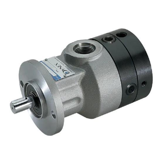
The pump nameplate is located on the flat surface between
the inlet port and the mounting flange. See FIGURE 1.
This stamped metal tag includes either a ten-digit model
number (i.e., PF2006-1808) or a descriptive model code (i.e.,
PF1002H-SXEA-22-10). The serial number, also stamped on
the plate, can be helpful when communicating with the sales
department.
Confirm Pump Capability
Refer to the published pump specifications. Exceeding the
performance recommendations will reduce operating life.
Contact the sales department for a review of any application
which requires operating above rated pressures or flows, or
beyond the specified speed range.
FIGURE 1: Typical pump showing location of nameplate and shaft
rotation tag, adjacent to inlet port. Rotation is indicated only on
pumps which are unidirecional (do not have bi-directional shaft rota-
tion). Refer to "Pump Rotation" on page 2.
PV4018-2928
123456
Checkball hydraulic pumps are axial piston pumps, which use two
check valves in each piston pumping chamber to direct flow from
the inlet side of the pump to the pump outlet port. During operation,
a fixed-angle wobble plate rotates with the drive shaft. The angled
surface imparts a reciprocating motion to the pistons, which move in
and out of the bores in the stationary barrel.
Be Aware of Design Changes
Dynex reserves the right to change designs and specifications
at any time without incurring any obligation. Contact the sales
department if you have any questions about pump operating
parameters, proper installation or operation.
INSTALLATION INSTRUCTIONS
Inlet Pipe/Hose Sizing
1.
Recommended maximum inlet fluid velocity is 4 feet per
second (1,2 metres per second).
2. Recommended maximum outlet fluid velocity is 30 feet
per second (9,1 metres per second).
Inlet Conditions
1.
Failure to meet minimum inlet pressure requirements will
result in reduced output flow.
IMPORTANT: Refer to the "Minimum Inlet Pressure" table
on page 6.
2.
Inlet pressures higher than 10 psi (0,7 bar) require a high-
pressure shaft seal. On most Dynex pump models a high-
pressure seal is an option that must be specified. Refer to
the published pump specifications.
SERVICE
INSTRUCTIONS
Advertisement
Table of Contents

Summary of Contents for Dynex PF500-10
-
Page 1: General Instructions
6. Inlet pressures higher than 10 psi (0,7 bar) require a high- pressure shaft seal. On most Dynex pump models a high- FIGURE 1: Typical pump showing location of nameplate and shaft pressure seal is an option that must be specified. Refer to rotation tag, adjacent to inlet port. -
Page 2: Operating Recommendations
Maintain angular and radial alignment within the Port/Fitting Configurations coupling manufacturer's specifications for your application. Dynex pumps are available with outlet ports suitable for Dynex recommends that the shaft alignment be within use at various pressure ranges. Refer to page 7 for port 0.005 inch (0,13 mm) TIR. -
Page 3: Initial Start-Up
Gate Valve and Relief Valve Be sure that any gate valve in the system is fully open to the pump prior to start-up, to avoid restricting flow to the inlet. 2. A relief valve in the circuit is required to protect against excessive pressures. - Page 4 2. Absolute cleanliness is necessary while working to pre- 3. Replace all seals and o-rings as standard hydraulic practice. vent contamination and potential pump damage. To assure correct assembly sequence and orientation, 3. To aid proper reassembly, note the relative position of the refer to the marks applied to the external surfaces (See housing, barrel and cover (some models).
-
Page 5: Troubleshooting
Testing Pump Rotation 2. All water glycol pumps are filled with an equipment preser- vative fluid prior to shipment from factory. Before start-up, look through the inlet port to assure piston shoes are seated properly. Manually rotate the shaft at least When storing for extended periods, keep the pump case two revolutions, to ensure that no binding is occurring. - Page 6 Minimum Inlet Pressure ➀ Operating Speed 1200 rpm 1500 rpm 1800 rpm 2400 rpm 2800 rpm 3600 rpm Pump Models Fixed Displacement Pumps: PF501 and PF504 PF507 ➁ ➁ PF510 � 1,0 ➁ ➁ ➁ ➁ PF1002 PF1003 and PF1004 ➁...
-
Page 7: Port Descriptions
PORT DESCRIPTIONS Dynex pumps are available with outlet ports suitable British Standard Pipe Ports for use at various pressure ranges. Contact the fitting High-pressure pumps are available with flat face ports manufacturer to ensure the selected fittings are rated for with British Standard Pipe (B.S.P.) parallel threads (BS... - Page 8 Cambs. PE19 8TT United Kingdom FAX: 262-691-0312 FAX: 508-881-6849 Tel: +44 [0] 1480 213980 E-mail: sales@dynexhydraulics.com E-mail: ashland@dynexhydraulics.com FAX: +44 [0] 1480 405662 E-mail: sales@dynexhydraulics.co.uk Copyright © Dynex/Rivett Inc. Printed in U.S.A. Bulletin PSI.CB-030 © Dynex/Rivett Inc. Printed in U.S.A. Bulletin PSI.CB-030 ©...