Table of Contents
Advertisement
Installation & Servicing Instructions
Baxi Bermuda BBU 15 HE
Condensing Back Boiler Unit
These Instructions must be read in conjunction with those for
the separate Valor Dimension electric firefront.
They include the Benchmark Commissioning Checklist
and should be left with the user for safe keeping.
© Baxi Heating UK Ltd 2009
Advertisement
Table of Contents

Related Manuals for Baxi Bermuda BBU 15 HE


Summary of Contents for Baxi Bermuda BBU 15 HE
- Page 1 Installation & Servicing Instructions Baxi Bermuda BBU 15 HE Condensing Back Boiler Unit These Instructions must be read in conjunction with those for the separate Valor Dimension electric firefront. They include the Benchmark Commissioning Checklist and should be left with the user for safe keeping.
- Page 2 Natural Gas Baxi Bermuda BBU 15 HE G.C.No. 44 075 09 For use with the following electric firefronts: Valor Dimension Classica Brass, Pewter or Black BBU Firefront Valor Dimension Dream Gold, Chrome or Black BBU Firefront Valor Dimension Innova BBU Firefront...
-
Page 3: Installer Notification Guidelines
Competent Person's Self Certification Scheme Install and Commission this appliance to manufacturer's instructions Complete the Benchmark Checklist If you notify via the ‘Gas Safe Register’, the register will issue the Building Regulations certificate on members’ behalf Scheme Members only Call ‘Gas Safe Register’ on: 0800 408 5577 or log onto: www.GasSafeRegister.co.uk... - Page 4 You can check your engineer is registered by telephoning 0800 408 5500 or online at www.GasSafeRegister.co.uk The boiler meets the requirements of Statutory Instrument “ The Boiler (Efficiency) Regulations 1993 N 3083” and is deemed to meet the requirements of Directive...
- Page 5 Where possible transport the boiler using a sack truck or other suitable trolley. Always grip the boiler firmly, and before lifting feel where the weight is concentrated to establish the centre of gravity, repositioning yourself as necessary. See the ‘Installation’ section of these instructions for recommended lift points.
-
Page 6: Table Of Contents
© Baxi Heating UK Ltd 2009 Contents Section Introduction General Layout Technical Data System Details Site Requirements Boiler Internal Wiring Installation Completion & Commissioning Annual Servicing 10.0 Changing Components 11.0 Setting the Gas Valve 12.0 Fault Finding 13.0 Short Parts List 14.0... -
Page 7: Introduction
© Baxi Heating UK Ltd 2009 1.0 Introduction Description 1. The Baxi Bermuda BBU 15 HE is a central heating boiler designed for installation within a builders opening in the living space of a dwelling. 2. The boiler is a fully automatic gas fired condensing boiler. -
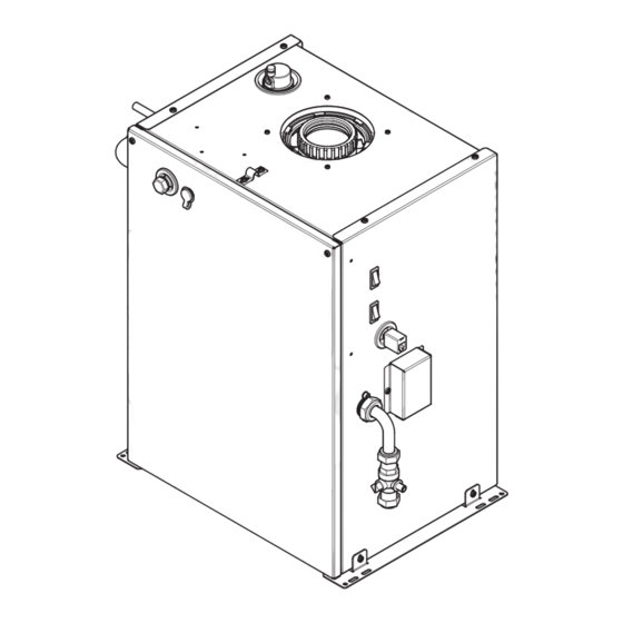
Page 8: General Layout
IMPORTANT: To commission the boiler it is is necessary to remove the Boiler Control from the firefront packaging and connect it to the boiler at the upper right hand side (item 6). - Page 9 Flue Kit (10m & 12.5m) (Fig. 3a) Terminal Cap Flue Duct Adaptor Air Cowl Air Duct Collar Air Duct Clamp Closure Plate Boiler Adaptor 60mm Ø Seal Collar Securing Screws x 4 100mm Ø Seal 60mm Ø Flue Duct 100mm Ø Air Duct ‘C’ Clip...
-
Page 10: Technical Data
Standard Assessment Procedure (SAP) for energy rating of dwellings. The test data from which it has been calculated has been certified by 0087. © Baxi Heating UK Ltd 2009 BBU 15 HE 3.0 Technical Data Bermuda HE CBBU 15 HE Appliance Type... -
Page 11: System Details
The static head must not exceed 30m of water. The static head must not be less than 1m of water. The boiler must not be used with a direct cylinder. Drain cocks should be fitted to all system low points. - Page 12 ›25°C) an external bypass must be fitted . 6. The bypass must be of the automatic pressure operated type. Storage Systems 1. For information regarding the use of a Bermuda BBU 15 HE boiler with a storage system, contact the appropriate storage system manufacturer.
- Page 13 It shall be positioned in the flow pipe either horizontally or vertically upwards and close to the boiler. No shut off valves are to be placed between the boiler and the safety valve. The valve should be installed with a...
- Page 14 Where a vessel of the calculated size is not available, the next available larger size should be used. The boiler flow temperature is controlled at approx. 75°C. The vessel size can now be determined from the information in table 1 where V = System volume in litres.
-
Page 15: Site Requirements
305mm minimum Fig. 9 © Baxi Heating UK Ltd 2009 5.0 Site Requirements Builders Opening (Fig. 9) 1. The boiler unit is designed to fit within a standard builders opening, the minimum dimensions of which are as shown. Height 570mm... - Page 16 2. Only one of the two available MULTIIFIT vertical concentric Flexi Flue kits approved for use with the boiler can be used (10m kit 720101701 or 12.5m kit 720102001). Any proprietary flue systems, terminals, adaptors etc. MUST NOT BE USED.
- Page 17 Gas Connection © Baxi Heating UK Ltd 2009 5.0 Site Requirements 1. No ventilation is required for the boiler in the room of installation. 1. The gas installation should be in accordance with relevant standards. In GB this is BS 6891. In IE this is I.S.
- Page 18 BS 6798 & Part H1 of the Building Regulations give further guidance. 2. If any further drain pipe is required (additional to that supplied with the boiler), it should be run in a proprietary material e.g. PVC, PVC-U, ABS, PVC-C or PP. John Guest ‘Speedfit’ components are recommended.
- Page 19 2. If the boiler reset rocker switch has been operated the pump will run also for 2 seconds. 3. When the level of condensate in the sump is sufficient to activate the discharge float switch the pump will run for 7 seconds, during which time about 0.6 litres of condensate will...
-
Page 20: Boiler Internal Wiring
8 7 6 5 4 3 2 1 Spark Generator - brown - black - blue - white - yellow 6.0 Boiler Internal Wiring Boiler Internal Illustrated Wiring Diagram Condensate Pump Gas Valve Ignition Electrode - green - green / yellow - red - grey... -
Page 21: Installation
© Baxi Heating UK Ltd 2009 7.0 Installation INSTALLATION SEQUENCE There are 4 main elements to the installation of the Baxi Bermuda BBU 15 HE:- • Preparation of pipework & opening • Inserting the flue into the chimney • Siting & fixing the boiler •... - Page 22 60mm flue duct. 16. In a similar way to fitting the boiler adaptor fit the air duct clamp to the air duct. This will prevent the duct falling back into the chimney (Fig. 27).
- Page 23 60mm lip seal into the first groove (Fig. 30). The flue duct adaptor can now be fitted in the same manner as the boiler adaptor (Fig. 31). 18. Fit the terminal cap over the flue duct adaptor and air cowl.
- Page 24 Carrying & lifting equipment should be used as required, e.g. when installing on another floor. 1. Lift the boiler from the packing base and place into the opening. 2. Align the boiler centrally as far back in the opening as possible, and ensure the distance between each side and the opening is equal.
-
Page 25: Completion & Commissioning
7. Ensure all external controls e.g. room stat, timer etc. are calling for heat and turn on the mains electrical supply. Turn the rocker switch at the top right of the boiler to ON. The fan and condensate pump will run briefly. - Page 26 IMPORTANT: The loose boiler serial number label supplied in the boiler kit must be applied to an area of the spacer frame that is visible to the end user e.g. lower right hand side.
-
Page 27: Annual Servicing
BS 7967, Parts 1 to 4. Check the Combustion Performance 5. Set the boiler to operate at maximum rate as described in Section 11.1.2 to 11.1.6. 6. Remove the threaded plug from the sampling point, insert the analyser probe and obtain the CO/CO be less than 0.004. - Page 28 Annual Servicing - Inspection 1. Ensure that the boiler is cool. 2. Ensure that the gas supply to the boiler is isolated. 3. Operate the Reset switch (Fig. 41) to activate the condensate pump and then repeat. This will empty most of the condensate from the sump.9.
-
Page 29: Changing Components
Fig. 48 10.0 Changing Components 10.1 Changing Components 1. To change any components on the back boiler it is necessary to remove the firefront. 2. Refer to the Installer Guide that accompanies the firefront for details of removal. 3. Ensure that the boiler is cool and that the electrical and gas supplies are isolated. - Page 30 5. Undo the combustion panel securing nuts and remove the special spring washers. Remove the complete fan & panel assembly from the boiler. Check the condition of the insulation piece. 6. Undo and remove the nuts and washers securing the fan to the gas/air inlet.
- Page 31 Gas/Air adjustment screw until it is flush with the valve body, then turn the screw 4 full turns clockwise (Fig. 51). If the boiler will not light, or the correct CO contact the ‘heateam’...
- Page 32 Flow Pipe Fig. 52 Clip Fig. 53 Fig. 54 Control Knobs Discharge Float Switch Alignment Bracket © Baxi Heating UK Ltd 2009 Safety Thermostat Safety Float Switch Fig. 55 10.0 Changing Components 10.9 PCB (Fig. 54) 1. Pull off the two control knobs and disengage the securing tabs of the cover.
-
Page 33: Setting The Gas Valve
- see Section 9.1 1. The combustion (CO boiler for several minutes. To do this it is necessary to set the boiler to ‘Calibration Mode’. 2. Ensure that all external controls are calling for heat. The actual current boiler temperature is shown on the display. -
Page 34: Fault Finding
To perform a Service Reset it is necessary to have access to the boiler. By pressing the Reset rocker switch on the right of the boiler case for a minimum of 5 seconds when error codes are displayed it is possible to reset the boiler once the fault has been rectified. - Page 35 Refer to Section 16.0 “Illustrated Wiring Diagram” for position of terminals and components Central Heating - Follow operational sequence Turn on Power Supply Display Illuminates Error 110 flashing Error 131 flashing Error 20 or 28 flashing Error 158 flashing Turn Central Heating thermostat to Maximum.
-
Page 36: Fault Finding Solutions Sections
Fault Finding Solutions Sections Is there 230V at: Main terminals L and N Main terminal fuse PCB - X1 connector terminals 1,2 Check all system wiring and pump Service Reset Condensate Pump does not run PCB - X3 connector terminals 5 & 6 for at least 2 seconds Condensate Pump terminals for at least 2 seconds... - Page 37 IMPORTANT:There is no limit to the number of repeated ‘Service Reset’ operations but the Boiler Control must be refreshed by ‘Restoring Boiler Control Default’ as described on p.34 following the final ‘Service Reset’ and © Baxi Heating UK Ltd 2009 Allow to cool.
-
Page 38: Short Parts List
© Baxi Heating UK Ltd 2009 13.0 Short Parts List Short Parts List Description Manufacturers Part No. Burner Assy 720125701 Injector 720126301 Ignition Lead 720127501 Gas Valve 720127001 P.C.B 720125801 5121447 NTC Sensor 720126101 Float Switch 720126201 (Safety or Discharge) Safety Thermostat 720126401 Spark Generator... -
Page 39: Notes
14.0 Notes © Baxi Heating UK Ltd 2009... - Page 40 14.0 Notes © Baxi Heating UK Ltd 2009...
- Page 41 14.0 Notes © Baxi Heating UK Ltd 2009...
-
Page 42: Benchmark Checklist
This Commissioning Checklist is to be completed in full by the competent person who commissioned the boiler as a means of demonstrating compliance with the appropriate Building Regulations and then handed to the customer to keep for future reference. Failure to install and commission this equipment to the manufacturer’s instructions may invalidate the warranty but does not affect statutory rights. -
Page 43: Service Record
SERVICE RECORD It is recommended that your heating system is serviced regularly and that the appropriate Service Record is completed. Service Provider Before completing the appropriate Service Record below, please ensure you have carried out the service as described in the manufacturer’s instructions. -
Page 44: Description
If you would like heateam to carry this out please call on 0844 871 1525. Our promise to you If you experience a fault with your new boiler, we aim to provide a safe and high quality repair service supported by our dedicated national network of highly skilled engineers.