Advertisement
Quick Links
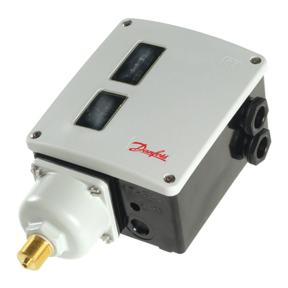
Installation guide
Pressure switch
RT 19W, RT19B, RT19S, RT 30AW, RT 30AB, RT 30AS, RT 31W, RT 31B,
RT 31S, RT 32W, RT 32B, RT 33B, RT 35W, RT 112W
Fig. 1
Fig. 4
ENGLISH
Fail safe pressure switches types:
RT 19W, RT 19B, RT 19S, RT 30AW, RT 30AB,
RT 30AS, RT 31W, RT 31B, RT 31S, RT 32W,
RT 32B, RT 33B, RT 35W, RT 112W
Data
Tested and approved by TÜV
(Technischer Überwachungs Verein)
The meaning of the type designation
letters is as follows:
A: Also approved for use in refrigeration plant
W: Pressure monitoring with automatic reset
B: Pressure limiter with external reset
S: Safety pressure limiter with internal reset
Contact load:
Max. ambient temperature:
Max. temperature of medium:
Max. test pressure:
RT 19, RT 32 (-W -B -S):
RT 30A, RT 31 (-W -B -S):
RT 33B, RT 35W, RT 112:
Min. test pressure:
Installation
A set of Pg13.5 cable gland is attached to
© Danfoss | DCS (jmn) | 2015.11
PED approved acc. to EN12953-9 and EN12922-11
5
9
38
the RT in a separate bag. To ensure IP66
(units with automatic reset) or IP54 (units
with external reset) grade of RT enclosure
it is necessary to assemble this gland as
shown in the fig. 4. If this gland is not used
with a cable, a metal blinding should be
also assembled.
Make the pressure connection so that any
impurities in the line do not block the
pressure inlet of the control.
For example, fit the pressure switch to an
upright connector (with the unit verti-
cal). Damp strong pressure pulsations.
A damping loop will often be sufficient.
Insert a water-filled loop as a temperature
barrier; a 10 mm Cu tube, for example, if
see fig.3
in a high temperature plant there is a risk
-40 °C – 70 °C
of the pressure connection to the control
150 °C
becoming heated to more than 100 °C.
In water plant, position the pressure
47 bare
switch so that it cannot be exposed to
25 bare
frost (let it operate on an air cushion, for
8 bare
example).
- 1 bar
Setting
The pressure switch must be set to provide
the function - make or break - on rising
Fig. 2
Fig. 3
Fig. 5
temperature (for RT 31, RT 32 and RT 33
on falling temperature). The setting can be
made with the setting knob (5) while at the
same time reading off the main scale (9).
See fig. 1. The differential must be set with
the differential setting disc (19) using the
nomogram in fig. 2.
Examples
1. RT 31W
The pressure on a steam boiler must be
controlled by an RT 31W.
Max. pressure 8 bar, min. pressure 7.5 bar,
differential 8-7.5 = 0.5 bar
1. Connect the oil burner to pressure
control terminals 1-2
2. Using the setting knob (5), set the
pressure control at 8 bar
3. Set the differential disc at approx. 3.5 in
accordance with the nomogram in fig. 2.
2. RT 19B or RT 19S
When the pressure in a boiler exceeds
20 bar, the RT 19 must cut off the burner.
Automatic restart must not occur.
IC.PI.P10.S2.51 | 520B6749 | 1
Advertisement

Related Manuals for Danfoss RT 30AW


Summary of Contents for Danfoss RT 30AW
-
Page 1: Installation Guide
Installation guide Pressure switch RT 19W, RT19B, RT19S, RT 30AW, RT 30AB, RT 30AS, RT 31W, RT 31B, RT 31S, RT 32W, RT 32B, RT 33B, RT 35W, RT 112W PED approved acc. to EN12953-9 and EN12922-11 Fig. 2 Fig. 3 Fig. - Page 2 Fail safe pressostater type: Wenn bei Anlagen mit hohen Temperaturen klemmer 1-2 RT 19W, RT 19B, RT 19S, RT 30AW, RT 30AB, die Gefahr besteht, das sich der Druckan- 2. Indstil pressostaten på 8 bar med RT 30AS, RT 31W, RT 31B, RT 31S, RT 32W, schluss des Pressostats auf über 100 °C...