Table of Contents
Advertisement
Your new Miter Saw has been engineered and manufactured to Ryobi's high standards for dependability, ease of opera-
tion, and operator safety. Properly cared for, it will give you years of rugged, trouble-free performance.
WARNING: To reduce the risk of injury, the user must read and understand the operator's manual before using
this product.
Thank you for buying a Ryobi tool.
SAVE THIS MANUAL FOR FUTURE REFERENCE
OPERATOR'S MANUAL
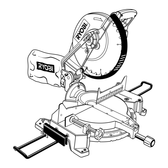
12 in. (305 mm) Compound Miter Saw
Model TS1551 - Double Insulated
Advertisement
Table of Contents

Related Manuals for Ryobi TS1551


Summary of Contents for Ryobi TS1551
- Page 1 Your new Miter Saw has been engineered and manufactured to Ryobi's high standards for dependability, ease of opera- tion, and operator safety. Properly cared for, it will give you years of rugged, trouble-free performance. WARNING: To reduce the risk of injury, the user must read and understand the operator's manual before using this product.
-
Page 2: Table Of Contents
Laser Guide ... 27-28 Maintenance ... 29 Parts Ordering/Service ... 30 Your saw has many features for making cutting operations more pleasant and enjoyable. Safety, performance, and dependability have been given top priority in the design of this saw making it easy to maintain and operate. -
Page 3: Rules For Safe Operation
For service we suggest you return the tool to your nearest RYOBI AUTHORIZED SERVICE CENTER for repair. When servicing use only identical Ryobi replacement parts. - Page 4 KEEP THE WORK AREA CLEAN. Cluttered work areas and work benches invite accidents. DO NOT leave tools or pieces of wood on the saw while it is in operation. DO NOT USE IN DANGEROUS ENVIRONMENTS. Do not use power tools near gasoline or other flammable liquids, in damp or wet locations, or expose them to rain.
- Page 5 REPLACEMENT PARTS. All repairs, whether electrical or mechanical, should be made at your nearest autho- rized service center. WHEN SERVICING, use only identical Ryobi replace- ment parts. Use of any other parts may create a hazard or cause product damage.
-
Page 6: Glossary Of Terms
The area over, under, behind, or in front of the blade. As it applies to the workpiece, that area which will be, or has been, cut by the blade. The distance that the tip of the saw blade tooth is bent (or set) outward from the face of the blade. Through Sawing Any cutting operation where the blade extends completely through the thickness of the workpiece. -
Page 7: Unpacking And Tools Needed
To release the saw arm, push down on top of saw arm and cut the tie-wrap. The following tools (not included) are needed for checking adjustments of your saw or for installing the blade: 12 mm COMBINATION WRENCH... -
Page 8: Loose Parts
The following items are included with your Compound Miter Saw: 12 in. (305 mm) Saw Blade Miter Lock Handle Dust Bag Dust Guide Stop Block Small Wing Screw Clamp Brackets (2) Clamp Bracket Screws (2) DUST BAG DUST GUIDE MITER... -
Page 9: Features
TABLE FRAME FEATURES 12 in. BLADE A 12 in. (305 mm) saw blade is included with your compound miter saw. It is fine for most wood cutting operations, but for fine joinery cuts or cutting plastic, use one of the accessory blades available from your nearest dealer. - Page 10 For convenience when carrying or transporting your miter saw from one place to another, a carrying handle has been provided on top of the saw arm as shown in figure 3. To transport, turn off and unplug your saw, then lower the saw arm and lock it in the down position.
-
Page 11: Features
SELF-RETRACTING LOWER BLADE GUARD The lower blade guard is made of shock-resistant, see- through plastic that provides protection from each side of the blade. It retracts over the upper blade guard as the saw is lowered into the workpiece. WARNING:... -
Page 12: Assembly
DUST BAG See Figure 9. A dust bag is provided for use on your miter saw. It fits over the exhaust port on the upper blade guard. To install it, remove dust guide from exhaust port. Then, squeeze the two metal clips to open the mouth of the bag and slide it on the exhaust port. -
Page 13: Table Extensions
The stop block is included with the table extensions and is useful as a stop for making repetitive cuts to the same length. It can be installed on either side of the saw base: Slide the stop block on the back arm of either table extension, then insert the table extensions into the saw base. -
Page 14: To Install Blade
WARNING: A 12 in. (305 mm) blade is the maximum blade capacity of your saw. Never use a blade that is too thick to allow outer blade washer to engage with the flats on the spindle. Larger blades will come in contact with the blade guards, while thicker blades will prevent the blade bolt from securing the blade on the spindle. -
Page 15: Adjustments
Always install the blade with the blade teeth and the arrow printed on the side of the blade pointing down at the front of the saw. The direction of blade rotation is also stamped with an arrow on the upper blade guard. - Page 16 Push down on the saw arm and pull out the lock pin to release the saw arm. Raise saw arm to its full raised position. Loosen the miter lock handle approximately one-half turn. Depress the miter lock plate and rotate the miter table...
- Page 17 The edge of the square and the saw blade should be parallel as shown in figure 21. If the front or back edge of the saw blade angles away from the square as shown in figures 22 and 23, adjust- ments are needed.
- Page 18 Failure to unplug your saw could result in accidental starting causing possible serious personal injury. Pull the saw arm all the way down and engage the lock pin to hold the saw arm in transport position. Loosen the miter lock handle approximately one-half turn.
-
Page 19: Operation
The saw arm should rise completely to the up position by itself. If the saw arm does not raise by itself or if there is play in the pivot joints, have saw repaired by at your nearest RYOBI AUTHORIZED SERVICE CENTER. - Page 20 TO CROSSCUT WITH YOUR MITER SAW Pull out the lock pin and lift saw arm to its full height. Loosen the miter lock handle. Rotate the miter lock handle approximately one-half turn to the left to loosen.
- Page 21 0 BEVEL SCALE Pull out the lock pin and lift saw arm to its full height. Loosen the miter lock handle. Rotate the miter lock handle approximately one-half turn to the left to loosen.
- Page 22 TO MAKE A COMPOUND CUT WITH YOUR MITER SAW Pull out the lock pin and lift saw arm to its full height. Loosen the miter lock handle. Rotate the miter lock handle approximately one-half turn to the left to loosen.
- Page 23 Long workpieces need extra supports. Supports should be placed along the workpiece so it does not sag. The support should let the workpiece lay flat on the base of the saw and work table during the cutting operation. Use the optional work clamp or a C-clamp to secure the workpiece.
- Page 24 CUTTING COMPOUND MITERS To aid in making the correct settings, the compound angle setting chart below has been provided. Since compound cuts are the most difficult to accurately obtain, trial cuts should be made in scrap material, and much thought and planning made, prior to making your required cut.
-
Page 25: Cutting Crown Molding
CUTTING CROWN MOLDING Your compound miter saw does an excellent job of cutting crown molding. In general, compound miter saws do a better job of cutting crown molding than any other tool made. In order to fit properly, crown molding must be compound mitered with extreme accuracy. -
Page 26: Clamping Wide Workpieces
Bevel Angle Type of Cut Setting Left side, inside corner 1. Top edge of molding against fence ° 33.85 2. Miter table set right 31.62 3. Save left end of cut Right side, inside corner 1. Bottom edge of molding against fence °... -
Page 27: Laser Guide
See Figure 40. The laser guide will generate a red colored line on the work surface when the saw blade is spinning above 500 rpm. The red laser line will appear as a broken line on the workpiece when the blade assembly is in the uppermost position and the motor switch is activated. -
Page 28: Laser Guide
Failure to unplug your saw could result in accidental starting causing possible serious personal injury. Remove the laser guide from the saw. Lay laser guide on a flat surface with the two phillips screws facing upward. Remove the screws and separate the laser guide cover from the laser guide support. -
Page 29: Maintenance
If operation is dusty, also wear a dust mask. WARNING: To ensure safety and reliability, all repairs should be performed by a qualified service technician at a Ryobi Authorized Service Center to avoid risk of personal injury. Page 29... -
Page 30: Parts Ordering/Service
Ryobi Authorized Service Center. Be sure to provide all pertinent facts when you call or visit. Please call 1-800-525-2579 for your nearest Ryobi Authorized Service Center. You can also check our web site at www.ryobitools.com for a complete list of Authorized Service Centers.