Table of Contents
Advertisement
Your new Band Saw has been engineered and manufactured to Ryobi's high standards for dependability, ease of operation,
and operator safety. Properly cared for, it will give you years of rugged, trouble-free performance.
WARNING:
To reduce the risk of injury, the user must read and understand the operator's manual before using
this product.
Thank you for buying a Ryobi product.
SAVE THIS MANUAL FOR FUTURE REFERENCE
OPERATOR'S MANUAL
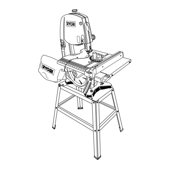
10 in. BAND SAW
BS1001SV
Advertisement
Table of Contents

Related Manuals for Ryobi BS1001SV


Summary of Contents for Ryobi BS1001SV
- Page 1 Your new Band Saw has been engineered and manufactured to Ryobi's high standards for dependability, ease of operation, and operator safety. Properly cared for, it will give you years of rugged, trouble-free performance. WARNING: To reduce the risk of injury, the user must read and understand the operator’s manual before using this product.
-
Page 2: Table Of Contents
n Introduction ... 2 n General Safety Rules ... 3 n Specific Safety Rules... 4 n Symbols...5-6 n Glossary of Terms... 7 n Electrical ... 8 n Features...9-10 n Tools Needed ... 11 n Loose Parts List...11-12 n Assembly ...13-16 n Operation...17-20 n Adjustments...20-23 n Maintenance ...24-25... -
Page 3: General Safety Rules
WARNING: Read and understand all instructions. Failure to follow all instructions listed below, may result in electric shock, fire and/or serious personal injury. READ ALL INSTRUCTIONS n KNOW YOUR POWER TOOL. Read the operator's manual carefully. Learn the applications and limitations as well as specific potential hazards related to this tool. -
Page 4: Specific Safety Rules
REPLACEMENT PARTS. All repairs, whether electrical or mechanical, should be made by a qualified service technician at an authorized service center. n WHEN SERVICING use only identical Ryobi replacement parts. Use of any other parts may create a hazard or cause product damage. -
Page 5: Symbols
Some of the following symbols may be used on this tool. Please study them and learn their meaning. Proper interpreta- tion of these symbols will allow you to operate the tool better and safer. SYMBOL NAME Volts Amperes Hertz Watt Minutes Alternating Current Direct Current... -
Page 6: Save These Instructions
The following signal words and meanings are intended to explain the levels of risk associated with this product. SYMBOL SIGNAL DANGER: WARNING: CAUTION: CAUTION: SERVICE Servicing requires extreme care and knowledge and should be performed only by a qualified service technician. For service we suggest you return the product to your nearest AUTHORIZED SERVICE CENTER for repair. -
Page 7: Glossary Of Terms
As it applies to the workpiece, that area which will be or has been cut by the blade. The distance that the tip of the saw blade tooth is bent (or set) outward from the face of the blade. -
Page 8: Electrical
60 Hz, AC only (normal household current). Do not operate this tool on direct current (DC). A substantial voltage drop will cause a loss of power and the motor will overheat. If the saw does not operate when plugged into an outlet, double check the power supply. ELECTRICAL... -
Page 9: Features
Net Weight... 82 lbs. (37.2 kg) (330 mm x 673.1 mm) RAPIDSET™ BLADE TENSION LEVER DUST BAG BLADE GUIDE KNOB BLADE GUIDE LOCK KNOB THROAT PLATE SAW TABLE BEVEL LOCK LATCH KNOB SCALE TRACKING VIEW WINDOW BEVEL ADJUSTMENT KNOB BLADE GUARD... -
Page 10: Miter Gauge
A sturdy metal fence guides the workpiece and is secured with the rip fence handle. SAW BLADE Saw comes with a standard 1/4 in. (6 mm) blade and a 3/8 in. (10 mm) blade. SAW TABLE WITH THROAT PLATE Your band saw has an aluminum saw table with tilt control for maximum accuracy. -
Page 11: Tools Needed
The following tools (not included) are needed for assembly and alignment: COMBINATION SQUARE The following items are included with your band saw: Hex Key, 3 mm ...1 Rip Fence ...1 Miter Gauge...1 Saw Table ...1 Extension Table ...1 Wing Nut...1... - Page 12 The following items are included with your band saw: Legs...4 Feet ...4 Mounting Bolts ...3 Flat Washers...3 Hex Nuts...3 Side Brace (right)...1 Side Brace (left) ...1 Top Brace (front and back) ...2 Leg Brace, Long ...2 Leg Brace, Short ...2 Carriage Bolts...16...
-
Page 13: Assembly
Failure to comply could result in accidental starting and possible serious personal injury. Assembly is best done in the area where the saw will be used. When you remove the table saw base, loose parts, and hardware from the packing materials, check all items with the loose parts list and drawing. - Page 14 Ignoring these precautions can result in back injury. n Place the band saw on the leg stand. Align the holes in the saw base with the holes in the upper braces.
- Page 15 Place a small combination square on the saw table beside the blade. n Loosen the bevel lock knob and rotate the bevel adjustment knob to tilt the saw table up or down to align table 90° to blade (0° position). Retighten the bevel lock knob.
- Page 16 Make sure RapidSet™ Blade Tension Lever is in the locked position. See Figure 14. n Before using the band saw, turn the blade tension knob on the top of the saw clockwise to engage tension. Check blade tension by the sound the blade makes (similar to plucking a guitar string).
-
Page 17: Operation
Before starting a cut, watch the saw run. If you experience excessive vibration or unusual noise, stop immediately. Turn the saw off, remove the switch key, and unplug the saw. Do not restart until locating and correcting the problem. CUTTING PROCEDURES n Hold the workpiece firmly against the saw table. - Page 18 AVOIDING INJURY n Make sure saw is level and does not rock. Saw should always be on a firm, level surface with plenty of room for handling and properly supporting the workpiece. n Bolt saw to the support surface to prevent slipping, walking or sliding during operations like cutting long, heavy boards.
- Page 19 Using the extension scale on the saw table, extend the saw table to the desired position. n Lock the saw table in place by turning the table lock knob clockwise. USING THE MITER GAUGE See Figures 18 - 19.
-
Page 20: Adjustments
USING THE RIP FENCE See Figure 20. n Unplug the saw. n From either side of the saw blade, slide the rip fence onto the saw table. Check for a smooth, gliding action. n Push the locking handle down to automatically align and secure the fence. - Page 21 Thread the blade through the saw table. n With the teeth of the blade toward the front of the saw and facing downward, place the blade through the lower blade guides and around the lower wheel.
- Page 22 NOTE: The thrust bearing screw is the set screw located on the front of the blade guide support. It is the set screw on the front of the saw housing below the saw table for the lower bearing. n Remove the blade guard by loosening the two screws.
- Page 23 The blade guides help keep the blade from twisting and binding. The blade will be ruined if the blade teeth hit the blade guides while using the band saw. The set of teeth and the sharpened edge of teeth will be damaged by hitting the blade guides.
-
Page 24: Maintenance
WARNING: When servicing, use only identical Ryobi replacement parts. Use of any other parts may create a hazard or cause product damage. WARNING: Always wear safety goggles or safety glasses with side shields during power tool operation or when blowing dust. - Page 25 Remove the top motor cap bolt while supporting the motor. n Pull the motor away from the band saw and slide the worn drive belt off of the pulley and discard. n Place new drive belt on motor pulley and slide drive belt over pulley while mounting the motor.
-
Page 26: Troubleshooting
Motor will not run. Blade does not run in the approxi- mate center of the upper wheel. Blade slows down when cutting. Blade breaking. Saw is noisy when running. Blade will not cut straight. Blade guides will not stay in position. TROUBLESHOOTING CAUSE 1. - Page 27 NOTES Page 27...
-
Page 28: Service Parts
Now that you have purchased your tool, should a need ever exist for repair parts or ser- vice, simply contact your nearest Ryobi Authorized Service Center. Be sure to provide all pertinent facts when you call or visit. Please call 1-800-525-2579 for your nearest Ryobi Authorized Service Center.