Ryobi AP1301 Operator's Manual
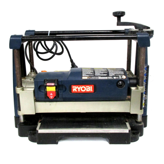
13 in. portable planer
Hide thumbs
Also See for AP1301:
- Manual del operador (24 pages) ,
- Operator's manual (22 pages) ,
- Repair sheet (7 pages)
Table of Contents
Advertisement
Your portable planer has been engineered and manufactured to our high standard for dependability, ease of operation, and
operator safety. When properly cared for, it will give you years of rugged, trouble-free performance.
WARNING:
To reduce the risk of injury, the user must read and understand the operator's manual before using
this product.
Thank you for your purchase.
SAVE THIS MANUAL FOR FUTURE REFERENCE
OPERATOR'S MANUAL
13 in. PORTABLE PLANER
AP1301
Advertisement
Table of Contents

Related Manuals for Ryobi AP1301


Summary of Contents for Ryobi AP1301
- Page 1 Your portable planer has been engineered and manufactured to our high standard for dependability, ease of operation, and operator safety. When properly cared for, it will give you years of rugged, trouble-free performance. WARNING: To reduce the risk of injury, the user must read and understand the operator’s manual before using this product.
-
Page 2: Table Of Contents
WHAT THIS WARRANTY COVERS: This warranty covers all defects in workmanship or materials in your RYOBI a period of two years from the date of purchase. With the exception of batteries, power tool accessories are warranted for ninety (90) days. -
Page 3: General Safety Rules
WARNING: Read and understand all instructions. Failure to follow all instructions listed below, may result in electric shock, fire and/or serious personal injury. READ ALL INSTRUCTIONS n KNOW YOUR POWER TOOL. Read the operator’s manual carefully. Learn the tool’s applications and limitations as well as the specific potential hazards related to this tool. -
Page 4: Specific Safety Rules
NEVER FEED THE WORK from the rear of the planer. n DO NOT ATTEMPT TO PERFORM an abnormal or little used operation without the use of sturdy and adequate jigs, fixtures, stops, and the like. - Page 5 SPECIFIC SAFETY RULES n ALWAYS STAY ALERT! Do not allow familiarity (gained from frequent use of your planer) to cause a careless mistake. ALWAYS REMEMBER that a careless fraction of a second is sufficient to inflict serious injury.
-
Page 6: Symbols
Some of the following symbols may be used on this tool. Please study them and learn their meaning. Proper interpreta- tion of these symbols will allow you to operate the tool better and safer. SYMBOL NAME Volts Amperes Hertz Watt Minutes Alternating Current Direct Current... - Page 7 The following signal words and meanings are intended to explain the levels of risk associated with this product. SYMBOL SIGNAL DANGER: WARNING: CAUTION: CAUTION: SERVICE Servicing requires extreme care and knowledge and should be performed only by a qualified service technician. For service we suggest you return the product to your nearest AUTHORIZED SERVICE CENTER for repair.
-
Page 8: Electrical
EXTENSION CORDS Use only 3-wire extension cords that have 3-prong ground- ing plugs and 3-pole receptacles that accept the tool’s plug. When using a power tool at a considerable distance from the power source, use an extension cord heavy enough to carry the current that the tool will draw. -
Page 9: Glossary Of Terms
Anti-Kickback Pawls (radial arm and table saws) A device which, when properly installed and maintained, is designed to stop the workpiece from being kicked back toward the front of the saw during a ripping operation. Arbor The shaft on which a blade or cutting tool is mounted. Bevel Cut A cutting operation made with the blade at any angle other than 90°... -
Page 10: Features
PRODUCT SPECIFICATIONS Feed Rate ...26 FPM No Load Speed ... 10,000 RPM Motor ... 2 HP Peak Input ... 120 Volt, 60Hz, AC Only, 15 Amps SWITCH POWER SWITCH WORK TABLE FEATURES Max Planing Height ... 6 in. Max. Planing Width ... 13 in. Max. -
Page 11: Loose Parts
HIGH-SPEED REVERSIBLE BLADES Two reversible high-speed blades provide twice the cutting life. POWER SWITCH AND SWITCH KEY Your planer has an easy access power switch with a remov- able switch key. THICKNESS SCALE The thickness scale accurately displays the height of the cutter blades to a maximum of 6 in. -
Page 12: Assembly
UNPACKING This product requires assembly. n Carefully remove the tool and any accessories from the box. Place it on a level work surface. NOTE: This tool is heavy. To avoid back injury, lift with your legs, not your back, and get help when needed. n Inspect the tool carefully to make sure no breakage or damage occurred during shipping. - Page 13 MOUNTING THE PLANER See Figure 4. If the planer is to be used in a permanent location, it is rec- ommended you secure it to a workbench or to a mounting board that can be easily clamped to a workbench or other stable surface.
-
Page 14: Operation
Do not lower the cutter head assembly lower than 3/16 in. n Do not use the planer set at the maximum depth of cut (1/8 in.) and at full width of cut (13 in.). Continuous use at maximum cutting capacity will damage the motor. - Page 15 OPERATION POWER SWITCH See Figure 6. The planer is equipped with a power switch that has a built-in locking feature. This feature is intended to prevent unauthor- ized and possible hazardous use by children and others. TO TURN THE PLANER ON: n With the switch key inserted into the switch, lift the switch to turn ON ( l ).
- Page 16 WARNING: To avoid serious personal injury, do not stand directly in line with the front or rear of the planer. If an object is thrown from the planer, it will travel in this direction. n Stand to one side of the planer infeed area.
-
Page 17: Adjustments
THICKNESS SCALE ADJUSTMENT See Figure 9. The thickness scale, located on the right front of the planer, shows the depth of the finished workpiece. Inaccurate cuts can be prevented by routinely checking the alignment of the thickness scale. -
Page 18: Maintenance
NOTE: With the dust hood removed, the cutter head lock will engage when the head is rotated. Do not operate the planer without the dust hood in place or the planer will be damaged. n Rotate the cutter head until the lock engages. This will correctly position one of the blades for removal. - Page 19 See Figure 13. Externally accessible brush assemblies are located at the right front and the left rear of the planer. These brushes should be inspected every 10 to 15 operating hours for wear. Replace both brushes when either brush has less than 1/4 in.
-
Page 20: Troubleshooting
Unit overloaded Circuit overloaded Solution Replace or turn cutter blades. Butt pieces end-to-end as they are fed into planer. Tighten lag bolts. Reduce depth of cut. Feed other end of board first. Replace or turn cutter blades. Dry wood before planing. - Page 21 NOTES...
-
Page 22: Parts Ordering / Service
Please record the model number and serial number in the space provided below. • HOW TO ORDER REPAIR PARTS When ordering repair parts, always give the following information: • MODEL NUMBER • SERIAL NUMBER Ryobi is a registered trademark of Ryobi ® 983000-828 10-13-05 (REV:00) OPERATOR’S MANUAL 13 in. PORTABLE PLANER...