Advertisement
g
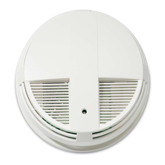
Description
The ESL 429/449 Series low-profile, self-diagnostic, two-wire and
four-wire smoke detectors work on the light scattering principle. A
pulsed infrared light-emitting diode serves as the light source, and a
high-speed photo-diode as the sensing element. This design has
superior protection against false alarms caused by dust, insects,
RF, and ambient light.
These smoke detectors are especially suited for residential
occupancies, including hotels, motels, and dormitories, as well as
other commercial and industrial fire-system applications. This
series is designed for two-wire and four-wire connection to 6-24
VDC fire alarm control panels, UL Listed for commercial or
household fire protection.
Features
Self-diagnostics including automatic sensitivity testing. Each
detector in the series continually monitors its own sensitivity and
operational status (see Maintenance).
A wide range of optional features are offered as shown in the
Product Selection Guide. To provide for almost any application,
these options include a built-in sounder, an auxiliary relay, an
integral heat detector, and an isolated heat detector.
Selecting a Location
Selecting a suitable location is critical to the operation of smoke
alarms. This equipment should be installed in accordance with the
National Fire Protection Association's (NFPA) Standard 72. See
Figure 1.
A-11-8.3.a Where to Locate the Required Smoke Alarms in
Existing Construction.
The major threat from fire in a family living unit occurs at night
when everyone is asleep. The principal threat to persons in
sleeping areas comes from fires in the remainder of the unit.
Therefore, a smoke alarm(s) is best located between the bedroom
areas and the rest of the unit. In units with only one bedroom area
on one floor, the smoke alarm(s) should be located as shown in
Figure 1 A.
In family living units with more than one bedroom area or with
more than one floor, more than one smoke alarm is required, as
shown in Figure 1 B.
In addition to smoke alarms outside of the sleeping areas, the
installation of a smoke alarm on each additional story of the family
living unit, including the basement, is required. These installations
are shown in Figure 1 C. The living area smoke alarm should be
installed in the living room or near the stairway to the upper level,
or in both locations. The basement smoke alarm should be installed
in close proximity to the stairway leading to the floor above. Where
installed on an open-joisted ceiling, the alarm should be placed on
the bottom of the joists. The alarm should be positioned relative to
the stairway to intercept smoke coming from a fire in the basement
before the smoke enters the stairway.
ESL 429/449
ESL 429/449 Series
Self-Diagnostic Photoelectric
Installation Instructions
California State Fire Marshal Approved
MEA (New York City) Approved
Where to Locate the Required Smoke Alarms in New Construc-
tion.
All of the smoke alarms specified for existing construction are
required and, in addition, a smoke alarm is required in each
bedroom.
A.
Dining
Room
B.
TV Room
Bedroom
C.
Bedroom
Living
Room
Basement
= Required smoke alarms
= Additional smoke alarms required for new construction
Figure 1 . Detector Location
Smoke Detectors
FM
APPROVED
Kitchen
Bedroom
Bedroom
Living Room
Bedroom
Dining
Kitchen
Bedroom
Room
Bedroom
Living Room
Bedroom
Dining
Room
1
Advertisement

Related Manuals for GE 429CT


Summary of Contents for GE 429CT
-
Page 1: Installation Instructions
ESL 429/449 Series Self-Diagnostic Photoelectric Smoke Detectors Installation Instructions California State Fire Marshal Approved MEA (New York City) Approved APPROVED Description Where to Locate the Required Smoke Alarms in New Construc- The ESL 429/449 Series low-profile, self-diagnostic, two-wire and tion. four-wire smoke detectors work on the light scattering principle. -
Page 2: Installation
4” (10cm) ceiling 4” acceptable here (10cm) never here 12” (30cm) Figure 3. Plug-in Terminal Block top of detector maximum acceptable here Note For instructions on removal of terminal block and Note side wall Measurements shown are to the circuit board, call technical services at 800-648-7424. closest edge of the detector. -
Page 3: Smoke Test
429 Series Wiring Diagram Models 429AT, 429C, Model 429CRT first detector last detector 429CT, 429CST not used power auxiliary * Two-Wire Compatibility power contacts Refer to ESL’s Compatibility Index for compatible control panel listings. Compatible Listed Control Unit* fire alarm... -
Page 4: Sensitivity Test
Sensitivity Test optical block chamber 1. Hold the magnet on the hinge side of the unit for more than one second (see Figure 7). The LED will flash 1 to 9 times. 2. Count the number of LED flashes, then use the following table to determine if any action is necessary. -
Page 5: Planning For Emergencies
3 years from the date of manufacture. During the warranty period, if a GE Security product or any of its WARNING components becomes defective, it will be repaired or replaced Do not enter a building where sirens are sounding without charge. -
Page 6: Product Selection Guide
Typ.Avg.Stby. Typ. Alarm Cur. Typ.Avg. Pol. Alarm Relay Other Relay (PK to PK) Cur. (12-24V) (12-24V) Rev.Cur. Contacts Contacts (uA) (mA) (mA) 429AT *see S09A 429C *see S10A 429CT *see S10A 429CRT *see S11A 429CST *see S11A 449C 449CT 449CRT 449AT 449CST 449CSRT 449CSRH ** 449CSTE...