Table of Contents
Advertisement
OWNER INSTALLATION AND
USER MANUAL Series 3000
Models 3214, 3314, 3316 & 3414
For Sectional Overhead Residential Doors Only
Before Starting Installation Read all Instructions Thoroughly
to Familiarize Yourself with All Aspects of Installation and Adjustment!
DOOR AND OPENER WILL NOT OPERATE PROPERLY UNTIL INFRARED SAFETY
SENSORS ARE INSTALLED AND PROPERLY ADJUSTED! DO NOT OPERATE DOOR
OPENER UNTIL FULLY INSTALLED, ADJUSTED & INSTRUCTED TO DO SO!
Installation... . . . . . . . . . . . . . . . .
Features... ... ... ... ... ... . .
Door Tests... ... ... . . . . . . . . . .
Pre-Assembly Check... ... ... ... .
Installation Instructions... ... ... ...
Installing Wall Station... ... ... . ...
Install Infrared Safety Sensors... ... .
and Programming... ... ... ... .
Travel Adjustment... ... ... ... ...
Obstruction Sensing Test... ... . . .
© Copyright 2003 Wayne-Dalton Corp.
Automatic Garage Door Opener
DO NOT USE ON ONE PIECE DOORS
2
4
5
5
6
8
9
14
16
16
19
18
19
CONTENTS
Wireless Keyless Entry Installation. . . . .
Mechanical lock Adjustment. . . . . . . . .
Operational Safety Rules... ... ...
Operation on Your Opener... ... ... .
Emergency Release Disconnect. . . . . .
Maintenance Schedule... ... ... . . .
Trouble Shooting... ... ... ... ...
Accessories... ... ... ... ... . . .
Warranty.... ... ... ... ... . . . . .
Part No: 307545
TM
20
21
22
22
23
24
26
27
28
29
30
31
32
New
6/18/2003
Advertisement
Table of Contents

Summary of Contents for Quantum 3214
-
Page 1: Table Of Contents
OWNER INSTALLATION AND USER MANUAL Series 3000 Models 3214, 3314, 3316 & 3414 Automatic Garage Door Opener For Sectional Overhead Residential Doors Only DO NOT USE ON ONE PIECE DOORS Before Starting Installation Read all Instructions Thoroughly to Familiarize Yourself with All Aspects of Installation and Adjustment! -
Page 2: Installation
Read These Important Safety Rules Before Proceeding This symbol indicates caution and appears throughout this instruction manual. This garage door opener is designed and tested to offer reasona- bly safe operation if installation is followed in strict accordance with these safety instructions. - Page 3 Veuillez lire ces règles de sécurité importantes avant de commencer les travaux Ce symbole vous demande de prendre les précautions voulues. Vous le trouverez d’un bout à l’autre du présent guide d’installation. Cet ouvre porte de garage a été conçu et essaye pour vous offrir un fonctionnement sécuritaire dans la mesure ou les directives d’installation sont respectées conformément a ces mesures de sécurité.
-
Page 4: Features
Automatic Garage Door Opener – For Residential Doors Only 1. Open and Close Cycle Control: Allows garage door to be started and stopped by push button, transmitter or wall station. The next impulse sends garage door in opposite direction. 2. Emergency Disconnect: Manual disconnect permit- ting operation of door during power failure with auto- matic reconnect when opener is reactivated. -
Page 5: Door Tests
Before you begin, complete the following two tests to insure that the door is balanced and working properly. A door that binds, sticks or is out of balance could cause severe injury. Do not attempt to compensate for an improperly adjusted door by the installation of an opener. -
Page 6: Installation Instructions
INSTALLATION INSTRUCTIONS Step 1: Attaching Motor Power Head Unit to Rail Before assembly, align sprocket/coupling cogs to match notches of driver gear. Rotate the Motor Spline to position Driver Gear so that the nearest notch in Driver Gear is directly behind Motor Spline, as illustrated. - Page 7 Step 3: Attach Unit to Front Wall Bracket Raise the front end of the opener and attach it to the front wall bracket, using the ¼” x 4” hex head bolt and the supplied ¼” plastic insert nut. Take care not to over tighten nut; tighten only until end of bolt is flush with outside of nut.
-
Page 8: Installing Wall Station
Do not mount wall con- trols near or next to garage door. Wired Wall Station: Wire the garage door opener wall station using bell wire (low voltage electrical wire) con- nected to COM and P.B. on vertical screw terminal strips, as illustrated. -
Page 9: Install Infrared Safety Sensors
Step 9: Installing Deluxe Wireless Wall Station (if included) Install all wall controls out of the reach of children and in a location where the door can be seen before activating. Do not mount push buttons near or next to ga- rage door. - Page 10 Step 12: Install Wireless Infrared Safety Sensors Wall Mounting Bracket (If Included) Select a mounting position 5 inches above the floor to center line of wall bracket. The EMITTER and TRANSPONDER units must be mounted inside the door opening to minimize any interference by the sun; however, the sensors must be mounted against the door track.
- Page 11 Step 15: Install Wired Infrared Safety Sensor Wall Mounting Brackets Use the following instructions if your opener is equipped with Wired Infrared Safety Sensors. If you just installed the Wireless Infrared Safety Sen- sors go to step 20. Select a mounting position 5 inches above the floor to center line of wall bracket.
-
Page 12: Install Wiring For Wired Infrared Safety Sensor
Step 17: Install Wiring for Wired Infrared Safety Sensor Identify which side of the garage door opening (if any) the sun is “likely” to shine on to. Since sunlight may affect infrared safety sensors, you should mount the sending unit on the side of the door opening exposed to the sun. - Page 13 Step 19: Mount Wired Infrared Safety Sensors Attach the sending and receiv- ing units to the “U” brackets by inserting their tabs into their respective holes. Step 20: Connecting Electrical Power To reduce the risk of electrical shock, connect the power cord only to a properly grounded 3 prong, 120 volt outlet.
-
Page 14: Wall Station Code Change And Programming
Step 21: Wireless Wall Station Security Code Change and Programming Note: The following steps describe the process to change the Wireless Wall Station security code and to program the Wireless Wall Station to the opener. IMPORTANT: You MUST change the Wireless Wall Station security code prior to programming the device to the power head unit. -
Page 15: Alignment Of Wireless Infrared Safety Sensors
Step 22: Alignment of the Wireless Infrared Safety Sensors Use the following instructions if your opener is equipped with Wireless Infrared Safety Sen- sors. If your opener is equipped with Wired Infrared Safety Sensors proceed to step 23. IMPORTANT: This infrared beam sensor sends an invisible beam of light from the emitter unit to the transponder unit across from the pathway of the door. -
Page 16: Infrared Safety Sensors Alignment
Step 23: Alignment of the Wired Infrared Safety Sensors Use the following instructions if your opener is equipped with Wired Infrared Safety Sensors. Otherwise proceed to step 24. IMPORTANT: This infrared beam sensor sends an invisible beam of light from the sending unit to the receiver unit across from the pathway of the door. -
Page 17: Connecting Cushion Arm To Trolley
Programming Transmitter to Power Head Unit Note: Do not press any button on the Transmitter until instructed 1. Press the PROGRAM Switch button located on the garage door power head unit once. The red PROGRAM STATUS light on the motor power head unit and overhead lamp will turn on and remain lit for one minute, indicating that it is ready to learn the Transmitter. -
Page 18: Obstruction Sensing Test
Step 27: Connecting Door Arm to Door Door Mounted Bracket Visually align cushion arm connecting hole with middle hole of door bracket by rotating tube section in appropriate direction. Release trolley (cushion arm attached) with manual release cord and pull trolley a few inches toward motor. Now rotate cushion arm tube section 2 turns counterclockwise to provide a cushion when door is closed or encounters an obstruction. -
Page 19: Transmitter Code Change & Programming 16 Travel Adjustment
Step 29: Setting Door Opening Travel Do not use adjustments to compensate for a poorly balanced door. This will interfere with the proper operation of the travel adjustments and may damage door. The door opener is assembled with the open travel adjustment preset for a typical door, but all doors should be adjusted to stop as close as possible to the door’s “natural”... -
Page 20: Wireless Keyless Entry Installation
Step 31: Programming Wireless Keyless Entry (If Included) NOTE: To facilitate installation, program the Keyless Entry station to the opener before mounting to wall. WARNING: During programming the garage door may operate. Keep people and objects clear of the moving door to prevent door damage or possible personal injury. NOTE: Before programming ensure garage door is in the “down”... -
Page 21: Opening & Closing Force Adjustment
Adjustment # 1 Opening and Closing Force This garage door opener is built with a safety system that allows the door to reverse in the close direction and stop in the open direction. This must be adjusted so your opener does not use excessive force in the down direction or react to the weight of the door during upward travel. -
Page 22: Contact Obstruction Sensing Adjustment. 22 Mechanical Lock Adjustment
If door reverses when it comes in contact with the floor, reset the door close limits according to instruction in Step 28. Adjustment # 3 Positive Mechanical Door Lock The garage door opener is designed with an automatic mechanical locking system. This lock secures the door in the fully closed position. -
Page 23: Operational Safety Rules
IMPORTANT SAFETY INSTRUCTIONS WARNING: To reduce the risk of severe injury of death: Before you proceed, please thoroughly read the safety rules on page 2 and the following operating instructions. Operate only when opener is properly adjusted and the door is visible and unobstructed. READ AND FOLLOW ALL INSTALLATION IN- STRUCTIONS. -
Page 24: Operation On Your Opener
HOW TO ACTIVATE THE OPENER Never let children operate or play with door controls. Keep remote control away from children. Use any of the following devices: 1. The Remote Control Transmitter; momentary push of the button and the door will start to move. 2. - Page 25 HOW TO OPERATE THE WIRELESS WALL STATION (If Included) Never let children operate or play with door controls. Keep remote control away from children. The Wireless Wall Station Provides the Following Features: 1. Momentarily pressing the UP/DOWN button activates the door. An open door will close and a closed door will open.
-
Page 26: Emergency Release Disconnect
HOW TO OPERATE THE DOOR MANUALLY – Emergency Release Disconnect The door should be fully closed if possible, weak or broken springs could allow an open door to fall rapidly. Property damage or serious personal injury could result. Do not use the manual release knob to pull the door open or closed. -
Page 27: Maintenance Schedule
MAINTENANCE OF YOUR OPENER SYSTEM Test door opener monthly. The garage door MUST reverse on contact with a 1 inch high solid test ob- ject on the floor. If adjusting either the force or the limit of travel, retest the door opener. Failure to ad- just the opener properly may cause severe injury of death. -
Page 28: Trouble Shooting
SYMPTOM Opener won’t work from wall button or radio control. Opener works from wall button but not from radio control. Door does not open and opener light flashes. Door does not open fully and light does not flash. Door stops and does not close fully. Door closes and then returns to fully open position and opener light flashes. -
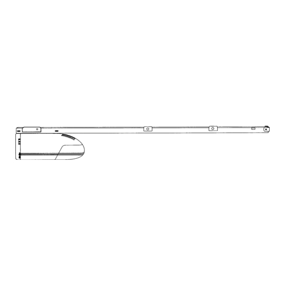
Page 29: Parts Breakdown-Rail Assembly
Parts Breakdown Rail Assembly – All Models... -
Page 30: Parts Breakdown-Power Head Assembly
Parts Breakdown Power Head Assembly – All Models Part # Description 157167 Frame 292123 Motor – 1/2 H.P. 306137 Motor Control Board (all models) 306364 Power Supply Cord 260570 Capacitor – 1/2 H.P. 306486 Wiring Harness 269025 Light Socket 260552 Lens 252994 MOV Surge Suppressor... -
Page 31: Accessories
Wireless Keyless Entry Multi-Function Wall Control Station Key Cable Outside Disconnect Outside Key Switch Extender Arm Assembly Kit Short Arm Assembly Kit Wire Spool Wire Reel QUANTUM ACCESSORIES Part#302083 Part# Part#302090 Part# 302078 Part# 297137 Part# 157277 Part#160383 Part#241171 Part#241172... -
Page 32: Warranty
LIMITED LIFETIME WARRANTY The Manufacturer warrants that the Quantum™ garage door opener will be free from defects in materials and workmanship for a period of five years (3214, 3314), ten years (3316), and fifteen years (3414). Electronic components are warranted for three years (3214, 3314) and five years (3316, 3414).