Table of Contents
Advertisement
Quick Links
Advertisement
Table of Contents

Related Manuals for Q-See QSD2216


Summary of Contents for Q-See QSD2216
- Page 2 About this document Before installing stand alone DVR, be sure to thoroughly review and follow the instructions in this Users Manual. Pay particular attention to the parts that are marked Also, when connecting with external application, first turn the power OFF and follow manual instruction for appropriate installation.
- Page 3 5. For questions and technical assistance of this product, contact Q-see. ►Strong recommendation on installation of the DVR unit 1. Verify that the electricity at the place you want to install the DVR unit is stable and meets our electrical requirements.
-
Page 4: Table Of Contents
5.8. USB BACKUP……………………………………………………………………………………27 5.9. STORAGE INFO…………………………………………………………………………………28 5.10. PTZ SET…………………………………………………………………………………………28 6. QUICK USER GUIDELINE……………………………………………………………………………29 7. USING THE NETWORK VIEWER……………………………………………………………………38 8. MAIN STANDARD & PARAMETER CHART……………...…………………………………44 9. TROUBLE SHOOTING GUIDE……………...……………...………………………………45 10. RECORD TIME TABLE……………...……...……………...…………………………………47 11. INTERNET VIEW/PLAYBACK CONFIGURATIONS………...………………………………48 Q-SEE PRODUCT WARRANTY…………………………………………………………………...51 CONTENTS... -
Page 5: Features And Function
1. FEATURE AND FUNCTION Video input: 16channels; Video output: 3channels. Audio input: 4channels; Audio output: 2channels. 16 alarm input and 1 relay alarm output. Compression mode: M-JEPG. Support network view. Support USB backup. Compatible with NTSC and PAL format. Support zoom, auto function, watermark security. Four optional levels of image quality: very high, high, low, very low. -
Page 6: Unit Description Of Front Panel
2. UNIT DESCRIPTION OF FRONT PANEL 2.1 Recording/Playing Control Buttons Area 1. REC: It is manual recording button. Press this button to record video to hard disk, Re-press this button, it will stop recording. So, this button is the switch button of manual recording and stopping recording operation, recording and stop will work simultaneously on 16 channels. - Page 7 1. Auto/1: Auto key, in shift mode, press this button, The DVR will be in auto dwell state, it dwells according to the time set in auto sequence set menu, and you can set the dwell time of each channel. Press this button to quit this mode. If not in shift mode, press this button to see big picture of channel 1.
-
Page 8: Rear Panel And System Connection
11. SF/0: Single frame forward button, in shift mode, while in playback state, long press this button can see single frame forward, press play button to play normally. If not in shift mode, press this button to see big picture of channel 10.while inputting numbers, this button is used as number key of”0”. -
Page 9: Back Panel And Connection Terminals
CH11 CH12 The DVR can connect 4 channel’s audio input, but you can only select one for recording. To display the DVR picture, the DVR video output signal should be transferred to your TV set or monitor. Any TV set that has a “video input” terminal is suitable for displaying the image. The figure above shows the video and audio signal line connection. - Page 10 2. Open/Close output A: N.O. Normal open, close when triggered. DVR must set as low voltage alarm. B: N.C. Normal close, open when triggered. DVR must set as high voltage alarm. Please refer to the picture below, channel 2 to channel 16 are the same as channel 1.
-
Page 11: Hard Disk Connection
3.4 Hard Disk Connection There are processing to install the hard disk. Note: If the DVR comes with a HDD pre-installed then skip the following steps. 1. Pull out the hard drive rack from DVR side panel. 3. Open the top cover of the drawer. -
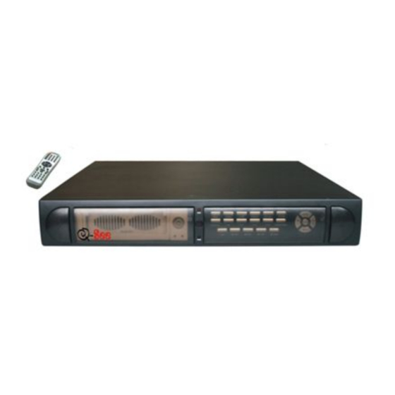
Page 12: Remote Control
4. REMOTE CONTROLLER 0 – 9, 10+: Select the channel (Full screen) 2x2: 2x2 Screen Modes 3x3: 3x3 Screen Modes 4x4: 4x4 Screen Modes USB: USB Storage Backup AUTO: Auto Sequence Mode ZOOM: 2X Zoom FREEZE: Freeze DISPLAY: Hard Disk Information MENU/EXIT: System Setup SEARCH: Time Search, Event Search and Start Stop Search ENTER: Enter Next Menu... - Page 13 If you enter the correct password, the main menu will display ad below.
-
Page 14: System Setup
5.2 SYSTEM SETUP Press “ENTER” button to enter sub menu PLAY REPEAT: Set the Playback Repeat VIDEO SYSTEM: Set the NTSC/PAL BUZZER SOUND: Set the Buzzer On/Off 5.2.1 TIME/DATA SET Set the date and time. DATE: Set the date TIME: Set the time FORMAT: Set the time display format (USA, EURO and Asia Users) DISPLAY: Set the time display on/off LOCAL: Set the time display position... -
Page 15: Hdd Format Set
5.2.2 HDD FORMAT SET Format the hard disk. Select “YES”, to format the hard disk. And all video on the HDD will loss. 5.2.3 FACTORY RESET Initialize all the setup; the DVR will reset to factory default settings. -
Page 16: Change Password
When the cursor moves to CHANGE PASSWORD, please press the enter button, and the Change Password window will appear. Password Level: password type of the DVR, the DVR has various types of password: SETUP: If set to “YES”, you have to input password to enter menu. -
Page 17: Firmware Update
When the cursor moves to FIRMWARE UPDATE, please press enter button, and the firmware update window will appear. Update Method: There are two methods to update the DVR firmware, USB (for USB thumb drives) and Network (not support) USB update: create a new folder named “firmware” in the USB thumb drive’s root directory, copy the update file to the folder, and plug in the USB thumb drive. -
Page 18: Display Setup
5.3 DISPLAY SETUP BOUND COLOR: Set the Color of Video Boundary (BLACK / WHITE / GRAY). BLANK COLOR: Set the Background Color of Loss Video (BLACK / WHITE). 5.3.1 CAMERA NAME SET When the cursor moves to Camera Name, please press the Enter button, the Camera Name Setup window will appear. -
Page 19: Color Set
Each channel’s name is a combination of six eight characters. Press up or down button to select each character, press LEFT or RIGHT button to modify each character, and then press enter button to save this name. DISPLAY: if Display is set to “OFF”, the channel’s name will not display on the screen. 5.3.2 COLOR SET When the cursor moves to Color Set, please press the Enter button, the Color Setup window will appear. -
Page 20: Auto Sequence Set
HDD is full. If set to “NO”, the DVR will automatically stop recording when the HDD is full. If there are two HDD in the DVR, when the MASTER HDD is full, the video will store to the SLAVE HDD, and when the SLAVE HDD is also full, the DVR will overwrite... -
Page 21: Audio Ch Set
REC SPEED: the recording frame rate of the DVR, factory default setting is 30F/SEC under NTSC (25F/SEC under PAL). This means the DVR records the events at the speed of 30 shots of frames per second. The higher of the record frame rate, the more natural look will be displayed on the screen when you playback the footage. -
Page 22: Rec Ch Set
When the cursor moves to Network Set, press the Enter button, and the network setup window will appear. Please note if the Netviewer software is connected to the DVR. You cannot access this menu unless you close the Netviewer software. -
Page 23: N/W Enable Set
IP MODE: the DVR has 2 IP modes, STATIC IP and DHCP, if you select STATIC IP, you can set the IP address manually, if you select DHCP mode, the DVR will automatically get the IP address. For STATIC IP, press UP or DOWN button to move the cursor among the digits, you can press LEFT and RIGHT buttons to modify the digits, press enter to save you change. -
Page 24: Mac Set
When the cursor moves to Mac Set then press the Enter button, the Mac Set window will appear. If you have more than one DVR in a local area network, you have to set each DVR to have an exclusive MAC address, but remember that you have only one chance to modify the MAC address, once you have changed the MAC address, this menu will not appear again. -
Page 25: Motion Detection Settings
ALARM ENABLE: alarm trigger switch, can be set to off, N.C(normal closed) or N.O(normal open). If users set it to off, the DVR will ignore the alarm input. MOTION ENABLE: Motion alarm switch, can be set to ON or OFF. If set to off, the DVR will ignore the motion alarm. -
Page 26: Motion Area Set
When in night as below, please set to normal level. Note: the above suggestions are a guide only based on testing in a general environment. You will need to select the best parameters according to the actual operation environment you are covering. -
Page 27: Schedule Set
5.7 SCHEDULE SET When the cursor moves to Schedule Set, press the Enter button, and the schedule setup window will appear. You can change a recording schedule during a day by using this setup window. Please note: Military time must be used. START: start record time STOP: stop record time SCHEDULE ENABLE: must set to “on”, if want to enable schedule record function... -
Page 28: Storage Info
When the cursor moves to PTZ Set, press the Enter button, and the PTZ Set window will appear. You must set the correct protocol so you can control a Pan Tilt camera (Speed Dome) via the DVR. Press the UP or DOWN button to move the cursor, and press LEFT or RIGHT to change the value. -
Page 29: Quick User Guideline
Fit the hard disk to the removable caddy and insert the removable caddy into the housing, then lock it up (turn the hard disk lock to the right) and connect the power which will then boot the DVR and it will start to work. - Page 30 6.4 Alarm Recording Alarm recording is not started by manually pressing the Record button, it is automatically activated once Schedule mode is enabled. Alarm recording can be activated by alarm input signal or motion, if the connection of alarm input equipment is correct, stable and reliable, and the alarm settings are correct.
- Page 31 recording is playing to see faster playback. Press the PLAY button to return to normal speed playing from the current place. Continuous pressing of the FWD button will change the fast-forward between four levels of speed (X2, X4, X8, X16,) in sequence. Continuously pressing the REW button will change the fast backward playback between four levels of speed (X2, X4, X8, X16) in sequence.
- Page 32 6.8 Time Search Move the cursor to Time Search, then press the Enter button and the Time search window will appear, which is illustrated as below. The red block below the number means there is recorded video at that time. Press the LEFT and RIGHT buttons to move the cursor along the year, month, day, hour and minutes.
- Page 33 If you want to search from MASTER HDD to SLAVE HDD, press the SERACH button, and then press Enter button. Press the Menu button to exit. 6.10 Record Search Move the cursor to the Record Search, press the Enter button, and the record search window will appear, which is illustrated as below.
- Page 34 If you want to use this function, the first step is to format USB device with “FAT” system on your computer. NOTE: the DVR doesn’t support “FAT32” file system. Plug in the USB device, go to the menu of Backup set, check whether the USB device was detected, and there is enough free space of the USB device, select the backup mode, then completely exit the menu system.
- Page 35 Using your PC to create a folder called “firmware” in the root directory of your USB memory stick, copy the update files to the folder. Plug the USB device into the DVR, go to the menu of Backup set, check that whether the USB device was detected, go to the Firmware Update menu and select USB method, move to Update Start and press Enter button and the update will start.
- Page 36 6.14 Information Display In shift mode, press display button, the main information of the DVR will display on screen. HDD SIZE: the size of the hard disk HDD USED: the used space of the hard disk. HDD READ: current HDD address for playback OVERWRITE: overwrite time of the HDD NETWORK IP: IP address of the DVR.
- Page 37 Note: When DVR is in PTZ mode, “REC” button is used as “ZOOM”; “PLAY” button is used as “IRIS”; “REW” button is used as “FOCUS”; “FWD” button is used as “SPEED”. “ADD” and “DEC”...
-
Page 38: Using The Network Viewer
7. USING THE NETWORK VIEWER Using the net viewer software, you can view the DVR through Internet or Intranet, also, you can view and backup the video data on the HDD through a computer. Open the software; you will see the... - Page 39 Enter the IP address and click “OK” button. 7.2 Viewer connect Press bottom, you can see the login box. Enter the correct password and click ok to login DVR. <Connect success> <Connect fail >...
-
Page 40: Live Play
After clicking “Playback” tab, net search window will display. First, you have to select the HDD of the DVR. Click the “Get record list” or “Get event list”, if the DVR has record list, you can see the window below: Double click the record list;... -
Page 41: File Play
7.5 Scandisk Connect the HDD that used in the DVR to a PC and then select Scandisk, Scandisk window will displa y, click and select one HDD, then you can play all the video on the HDD. 7.6 File Play Press “FilePlay”... - Page 42 7.7 Save to AVI To record the video to your PC’s HDD with “.avi” file system, just click" AVI" button, and the following window will pop-up Here, select the record channel and click "+" icon to define the file name and save path and click "ok" to start the AVI save.
-
Page 43: Ptz Control
7.8 Save to DVR To record the video stream to your PC’s HDD , just click" DVR" button and the video stream will be saved in the directory that you set (the default directory is c:\DVR\) Note: to play the file saved to DVR, just click "FilePlay" tab to open it. -
Page 44: Main Standard & Parameter Chart
8. Main standard & parameter chart Item Compressed picture Video signal Video input Video output Audio input Audio output Alarm input Alarm output Record time Electron clock Secrete function Update Power source Environment temperature weight Exterior size Specification M-JPEG NTSC/PAL Conposite:1.0Vp-p/75Ω,BNC×16 Conposite:1.0Vp-p/75Ω,BNC×2 S-VIDEO -8Db 22KΩ,RCA connector×4... -
Page 45: Trouble Shooting Guide
Q. What happens if I install my PC hard disk drive into the DVR? A. You can use a PC hard disk drive in the DVR. However, once it runs in DVR, it will delete any PC operation system and files on the hard disk drive. - Page 46 Q. I press record button, but the DVR does not start recording, why? A. Press display button to see if there is a hard disk detected, also if the DVR is in schedule mode (there is a “S” on the screen in yellow), you cannot start recording by press record button, you have to press schedule button again to cancel schedule mode.
-
Page 47: Record Time Table
Q. How do I change the On Screen Display (OSD) language on the DVR? A. You can change the OSD language from the default English to German, French, Italian, Polish, or Spanish by following the steps below. To change the OSD language, enter the menu system by pressing the MENU button on the front of the DVR and correctly input your password. -
Page 48: Internet View/Playback Configurations
Internet access (if the router is connected to a modem). 11.2 Network Configurations After connecting to Internet, DVR users should make the following configurations to make remote view/playback. 1): When in LAN, network administrators should open the following ports for specifics computers: 5000- 5002. - Page 49 3): In case you connect to Internet by proxy server, users should utilize port mapping software and open ports 5000, 5001, and 5002 for the surveillance computer. 4): In case users connect to Internet by router, then users should add the IP address of the surveillance computer and open the above mentioned ports in DMZ setup or Virtual Server setup (the names maybe different in various other kinds of routers) of the router.
- Page 50 IP of the router.) You may also have to place the IP address of the Swann DVR in the “DMZ” of your Firewall to enable the remote viewing interface. Information on how to do this should be detailed in the documentation covering operation of your Firewall.
-
Page 51: Q-See Product Warranty
Q-SEE Product Warranty Thank you for choosing our products. All of our products users have a conditional free warranty repair service for hardware within 12 months starting from purchase date, and a free exchange service within one month (valid for manufacturing defects). Permanent upgrading service is provided for the software. -
Page 52: Customer Information Card
Customer Information Card User’s Name Company Name Postal Address Postal code Phone Number E-mail Model Number of Product Serial Number of Product Purchase Date Distributor The material in this document is the intellectual property of our company. No part of this manual may be reproduced, copied, translated, transmitted, or published in any form or by any means without our company’s prior written permission.