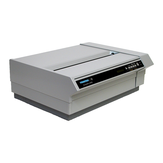
Printek FormsPro 4300 Operation Manual
Serial matrix printers
Hide thumbs
Also See for FormsPro 4300:
- Owner's manual (167 pages) ,
- Quick reference manual (6 pages) ,
- Quick reference manual (6 pages)

Related Manuals for Printek FormsPro 4300


Summary of Contents for Printek FormsPro 4300
- Page 1 FormsPro 4300, FormsPro 4500 and FormsPro 4503 SERIAL MATRIX PRINTERS Operation Manual Copyright 1994 Printek, Inc. 1517 Townline Road Benton Harbor, MI 49022 (616) 925-3200 Printek Part Number 2975...
- Page 2 VDE - GENERAL PERMIT USERS MANUAL INFORMATION Certificate of Manufacturer/Importer This is to certify that the FormsPro 4300, FormsPro 4500, and FormsPro 4503 printers are shielded against radio interference in accordance with the provisions of VDE 0871/6.78. The German Postal services have been advised that this device is being put on the market and are entitled to inspect the series for compliance with the regulations.
-
Page 3: Table Of Contents
INTRODUCTION TO SETUP Entering the Forms Setup Menu Entering the Interface Setup Menu CHANGING THE PAPER CHANGING THE RIBBON Using Printek Ribbons Removing the Old Ribbon Installing the New Ribbon CHAPTER 4 - USING SPECIAL FEATURES UNLOADING AND SELECTING FORMS... - Page 4 Possible Cloning Errors Information that is Cloned USING A SETUP UNIT FOR CLONING Cloning from a Printer to a Setup Unit Cloning from a Setup Unit to a Printer APPENDIX I - PRINTER SPECIFICATIONS APPENDIX J - SETUP MENU SUMMARIES...
-
Page 5: Introduction
This manual provides information on how to install and operate your FormsPro 4000 series printer. Below is a brief description of the information that is presented in each section. For your convenience, a glossary of printer related terms is included at the back of this manual. -
Page 6: Printer Model Descriptions And Key Features
The Printek FormsPro 4000 series printers are heavy duty serial dot matrix printers. The FormsPro 4300 is a medium speed printer and the FormsPro 4500 and FormsPro 4503 are high-speed printers. They have been specifically designed for printing on hard to print forms which are often not printed adequately by other printers. -
Page 7: Chapter 2 - Installation And Quick Setup
SELECTING AN APPROPRIATE INSTALLATION LOCATION The FormsPro 4000 series printers are designed to be installed on a Printek print stand, or on an open-top print stand that allows paper to be fed through the paper supply slot on the bottom of the printer. Since the printer also draws air through this slot for cooling, make sure that no part of the print stand obstructs this slot. - Page 8 Installation and Quick Setup Power Switch on Side of Printer. Power Cord Connector. Mounting Screws for Static Suppression Tinsel. Page 2-2...
-
Page 9: Installing The Ribbon
INSTALLING THE RIBBON To install the ribbon, first lift the lid on the top of the printer; then lift the ribbon loading bail as shown below. 1. Ribbon Loading Bail in up (open) position. 2. Ribbon Support Brackets. Unpack the ribbon from its shipping container and remove the retainer from the slot on top of the cartridge if present. - Page 10 Installation and Quick Setup Ribbon Cartridge Installation. Next lower the ribbon loading bail as shown below. This automatically places the ribbon between the ribbon guides and the print head as the print head is placed back into the printing position. Lowering (closing) Ribbon Loading Bail.
-
Page 11: Installing Paper
INSTALLING PAPER If the printer is not currently turned on, push the ON-1 side of the power switch on the right side of the printer. After you turn on the printer, it performs several self tests. If the printer is a FormsPro 4503, these tests also make sure that the tractors are properly positioned after shipment. - Page 12 Note that the forms do not extend above the tractor doors. The FormsPro 4300 and FormsPro 4500 have only one set of tractors which are positioned in the same location as the front tractors in the above picture. To install forms in the other sets...
- Page 13 Installation and Quick Setup FormsPro 4503 With Forms in All Tractor Paths. Center Path Positioned for Loading. Page 2-7...
-
Page 14: Testing The Printer
Installation and Quick Setup TESTING THE PRINTER When you turn the printer on, it automatically performs a series of self tests to assure that the electronics and printer mechanisms are operational. In the FormsPro 4503, the shuttle mechanism, which positions the tractors, also realigns itself if there is no paper installed or the paper is not positioned above the tear bar. -
Page 15: Entering The Interface Menu At The Control Panel
If the printer is online (ONLINE indicator is on), press the ONLINE button on the front of the printer to take the printer offline. This will cause the ONLINE indicator to turn off, and the display will momentarily show an “OFFLINE”... -
Page 16: Parallel Interface
“Data Bits:” function. Use the VALUE UP button to select either 7 or 8 data bits as required by your computer and/or software. This will normally be set to 8. Finally, press the SETUP button to exit the setup mode and reset the printer. The printer is now ready to receive parallel data. -
Page 17: Matching The Printer To Your Application Software
Digital Equipment Corporation's LA-120, a simple TTY emulation mode (which ignores most control codes and escape sequences), and a special Printek emulation mode. The Printek emulation may be used at any time to control features which are not supported by the Signal Chassis ground. -
Page 18: Selecting Epson Emulation
If the printer is online (ONLINE indicator is on), press the ONLINE button on the front of the printer to take the printer offline. This causes the ONLINE indicator to turn off, and the display to momentarily show an “OFFLINE”... - Page 19 Enter the interface menu as previously described. Press the FUNCTION UP button to display “Mode: n”. Then use the VALUE buttons to select “Printek”. Press SETUP again to exit the setup mode and reset the printer. Printek emulation is now selected.
-
Page 21: Chapter 3 - Operation
SETUP mode. All features which are modified during setup are stored in nonvolatile memory and are used each time the printer is turned on or reset. For more information, refer to the appendix on “Printer Reset Conditions”. The printer's control panel consists of six pushbutton switches, four LED indicators, and a 16- character LCD as shown below. - Page 22 This yellow LED indicates that the setup mode has been entered. The printer sounds a tone when it is directed to do so by a bell character (BEL) from the host computer. Other tones also alert operators of error conditions, such as...
-
Page 23: Control Panel Buttons
If paper is already loaded, this button uses the currently selected form length to advance the paper to the top of the next form. For a description of this button while the printer is in setup mode, refer to “Introduction to Setup” later in this chapter. - Page 24 NOTE: The tractor shuttle should always be parked whenever the printer is being transported. For a description of this button while the printer is in the setup mode, refer to “Introduction to Setup” later in this chapter.
- Page 25 Operation For a description of this button while the printer is in the setup mode, refer to “Introduction to Setup” later in this chapter. SETUP This button enters and exits the setup menus that are used to set parameters for up to ten unique form...
-
Page 26: Introduction To Setup
To exit the setup mode, press the SETUP button. While the printer is in a menu, you can use the FUNCTION UP and FUNCTION DOWN buttons to select any function. Whenever you select a function, its current value is displayed. - Page 27 F# Btm Mar: 0* through 255 Operation Description Allows you to select the desired form. The printer defaults to the currently selected form. Sets the tractor path to be used for the current form. This function is available only on the FormsPro 4503.
- Page 28 Operation Function Possible Values F# Scroll+: 0* through 127 F# Cut Adj: -85 to +84, 0*, or Auto F# Prnt Adj: -128 through 0*, or 0 through +127 Page 3-8 Description Sets the distance in lines from the top margin to the first print line of the form (does not add these lines to the form as the top margin does).
- Page 29 Function Possible Values F# Font: FX FD Epson FX FX DF Epson FX Draft FX LQ Epson FX PC FD PC DF PC LQ Proprinter PC EB FD EBCDIC EB DF EBCDIC Draft EB LQ EBCDIC Letter OCRA OQOCR-A OCRB OQ OCR-B PCL2 FD PC Latin 2 PCL2 DF PC Latin 2 PCL2 LQ PC Latin 2...
-
Page 30: Entering The Interface Setup Menu
The setup menu for interface parameters is the second setup menu. To enter this menu, first take the printer offline (refer to the ONLINE button described earlier). Then press and hold the SETUP button approximately two seconds until “Setup: INTERFACE” is displayed and the bell beeps twice to indicate that the second menu has been entered (Note that “Setup:... - Page 31 (TOF). Sets the number of seconds to delay before scrolling the top of form to the tear bar when the printer is idle and a form boundary has been reached. Page 3-11...
- Page 32 Operation Function Possible Values Fault: Break Pg*, or Reprint Pg Page Size: 256* or 512 through 28160 Chars: Control* or Printable Page 3-12 Description Selects whether a paper-out condition causes a Page Break or allows you to reprint the page. For more information, refer to “Page Reprint”...
-
Page 33: Changing The Paper
Opening The Latch Panel. While pulling out on this panel, lift the front of the printer to expose the paper tractors. The top of the unit will support itself in the up position while you load paper. - Page 34 If your printer is a FormsPro 4503, and you wish to install paper in the other tractor paths, you may do so at this time. If your printer is a FormsPro 4300 or FormsPro 4500, or if you do not wish to load other paths, proceed to the next paragraph. You can position the other tractor paths for loading without closing the printer's case.
- Page 35 FormsPro 4503 With Forms in All Tractor Paths. Center Path Positioned for Loading. Close the case of the printer by lowering it until the lower front panel closes. The printer LCD will display “Case Closed” when you do this. Check the LCD to make sure the correct form setup (0-9) has been selected. If necessary, press the UNLOAD/FORM SELECT button until the correct one is displayed.
-
Page 36: Changing The Ribbon
While it is possible to use non-Printek ribbons in your printer, doing so will limit the warranty on the print head and other mechanisms which are used to advance the ribbon fabric. If you choose to use non- Printek ribbons, you must disable the ribbon sensing system as described in the appendix titled “Advanced Control Panel Features”. -
Page 37: Installing The New Ribbon
Remove the old ribbon by lifting the left hand end of the ribbon off of the left support bracket. Then lift out the other end of the ribbon and set the ribbon aside. If the printer power is on, “Ribbon Removed” will be displayed as the ribbon is lifted out. - Page 38 Operation Lower the ribbon loading bail as shown below. This automatically places the ribbon between the ribbon guides and the print head as the print head is placed back into the printing position. Lowering (closing) Ribbon Loading Bail. Page 3-18...
-
Page 39: Chapter 4 - Using Special Features
This condition may occur if the host computer has sent part of a line, but has not terminated it with a Carriage Return, Line Feed, etc. To allow the printer to finish this line and/or form, simply press LOAD to reload the form and press ONLINE to allow the printer to complete the form. -
Page 40: Handling A Paper Error Condition
HANDLING A PAPER ERROR CONDITION Paper errors may be caused by either a paper out or a paper jam. The printer will deal with a paper error condition in one of two ways. The factory default method is described below under “Standard Paper Out Handling”. - Page 41 Using Escape Sequences With Page Reprint Enabled To reprint a page, the printer performs a carriage return at the top of the newly loaded form, and then reprocesses all data received for the incomplete page. If escape sequences have been used in the partially printed page, the printer may be left in a different state than when the page began printing originally.
-
Page 42: Using The Ribbon Check Feature
“Change Ribbon” message. Secondly, you must turn off this feature if you wish to use non-Printek brand ribbons in your printer. If you want to turn this feature off, set the “Ribbon Check:” function in the “Setup: OPTIONS” to “No”. For more information, refer to the “Advanced Control Panel Features”... -
Page 43: Printing Setup Information
Part or all of the setup configuration information may be printed. To do so, turn off the power switch on the side of the printer, then press and hold the SETUP button while you turn the power switch back on. The printer will display the message “Print SETUP?”. Continuing... -
Page 45: Chapter 5 - In Case Of Difficulty
48 hour turnaround, to a replacement printer shipped to you within 24 hours. For more information, contact the company where you purchased the unit or contact Printek Customer Service at the above toll free number. - Page 46 However, only Printek ribbons will allow the ribbon sensing system and ribbon wear indicator to function. To configure your printer to be able to use non-Printek ribbons, refer to the appendix titled “Advanced Control Panel Features”. Worn or damaged ribbon.
- Page 47 Possible Cause or Remedy Carriage path is obstructed. Clear the obstruction and turn the printer off and back on again to clear the error. Carriage shaft is dirty. Wipe completely with a clean cloth. Ribbon cartridge is worn or damaged and will not advance ribbon.
-
Page 48: Using The Hex Dump Mode
When an ETX is received by the printer, its hexadecimal representation is printed in the hex dump, but no ACK is sent to the host computer. When you use the printer in hex dump mode, we recommend that you configure the printer for parallel I/O, serial I/O with hardware handshake, serial I/O with XON/XOFF handshake, or CX/TX if installed. -
Page 49: Selecting A Quality Form
Open the case like you would normally do when you load paper. As viewed from the front of the printer, locate the AC cover in the right rear corner of the chassis. Then remove the screw that secures the cover to the bottom of the chassis. - Page 50 In Case of Difficulty The printer is now ready to be put back into service. Page 5-6...
-
Page 51: Appendix A - Advanced Control Panel Features A
Setup: OPTIONS The option menu is the third setup menu. To enter it, first take the printer offline. Then press and hold the setup button for approximately 4-1/2 seconds until “Setup: OPTIONS” appears on the display and the bell beeps three times. Note that while you hold the button, “Setup: FORMS”... - Page 52 Advanced Control Panel Features Function Possible Values Ribbon Life: 15*, 5 - 30 Paper Cutter: Yes or No* Imager: Yes or No* Translation: Off* or On Free Format: Off* or On Terminator: LF* or CR Ignore Char: Off* or On Zero: Normal or Slashed* Ignore Col 1:...
- Page 53 Function Possible Values Bar Codes: Hi-Res*, Med-Res, Lo-Res Advanced Control Panel Features Description This function is only available when an Imager option is installed. For more information, refer to the Imager manual. Page A-3...
-
Page 54: Setup: Security
The security menu is the fourth setup menu. To enter it, first place the printer offline. Then press and hold the setup button for approximately 8-1/2 seconds until “Setup: SECURITY”... - Page 55 When this completes, the security value is set to Edit. Used for cloning setup information to or from a printer. For more information, see the appendix on “Cloning Printer Setup”. Page A-5...
- Page 56 Advanced Control Panel Features Page A-6...
-
Page 57: Appendix B - Optional Rs-422 Interface
OPTIONAL RS-422 INTERFACE A 25-pin female “D” type connector is located on the rear of the printer above the power connector. Connect a shielded cable between your computer and this connector. The pin-out for this connector is shown below. RS-422 Serial Interface Connector To configure your printer for serial data, more information is required than for some other interfaces. -
Page 59: Appendix C - Optional Coaxial/Twinaxial Interface C
DIP switches (SW1-7 & SW1-8). interface will automatically switch to Printek emulation and select the EBCDIC font. The interface will automatically switch the printer to the default emulation selected in the Interface menu and select the parameters set for the current form in the Forms menu when data is received at the parallel port. -
Page 60: Option Switches When Configured For Coaxial Operation
Optional Coaxial/Twinaxial Interface In the DSC/DSE type LU3 mode, both formatted and unformatted data streams are supported. Interface diagnostics are available at the end of this appendix in the section titled “Coaxial/Twinaxial Interface Diagnostics”. Option Switches When Configured for Coaxial Operation The dipswitches as shown above have the following meanings when the interface is configured for coaxial operation. - Page 61 SW2-1 OFF* SW2-1 ON SW2-2 OFF* SW2-2 ON SW2-3 OFF* SW2-3 ON SW2-4 OFF* SW2-4 ON Optional Coaxial/Twinaxial Interface Long. Very Long (60 seconds). Run. Addr 0 = Logical Buffer Size is 1920. Addr 1 = Logical Buffer Size is 960. Addr 2 = Logical Buffer Size is 1920.
-
Page 62: Twinaxial Operation
0) will expect a response from a 4214 Model 01 at that address location. Should there be a 5256 Model 3 printer at device address 10 when the system sends a print job to the printer, the system would generate a “HARDWARE FAILURE” error message (for System 38) or a “PROGRAM ERROR”... -
Page 63: Option Switches When Configured For Twinaxial Operation
Option Switches When Configured for Twinaxial Operation The dipswitches as shown above have the following meanings when the interface is configured for twinaxial operation. An asterisk (*) indicates the factory default setting. Switch/Position SW1-1 SW1-2 OFF* OFF* SW1-3 OFF* SW1-4 OFF* SW1-5 SW1-6 OFF* OFF* SW1-7 SW1-8... -
Page 64: Twinaxial Installation Preparation
To put the printer on-line, perform the following steps: Step 1 - Power down the printer. Step 2 - If there are any active devices on the twinaxial line that the printer is going to be on, you must: Disable or remove the line termination on the device immediately up stream. -
Page 65: Twinaxial Verification Problems
“smart T” connector on the printer. If this printer is the first or only device on this line (only one cable is attached to the printer), the “smart T” will automatically provide the proper termination for the cable. -
Page 66: Coaxial/Twinaxial Interface Diagnostics
If the problem remains after you have checked all of the above, you may use the diagnostics described in the following section to verify that the interface and printer are functioning properly. If you are still unable to complete the installation, contact your dealer or Printek Technical Support for assistance. - Page 67 Verify the printer configuration. Check all of the installation connections. Rerun the diagnostic. If the problem persists, contact your dealer or Printek Technical Support for technical assistance. If possible, have the configuration printout from the Address 7 diagnostic available when you call.
- Page 68 Optional Coaxial/Twinaxial Interface Page C-10...
-
Page 69: Appendix D - Optional Buffer Expansion
Field installation, as described below, should be performed only by qualified service personnel. For installation, please contact the company who sold you the printer or contact Printek, Inc. Customer Service at 800-368-4636 for the name of the authorized service center nearest you. - Page 70 Be sure that the notch is oriented the same as the one just removed (notched end toward the front of the printer). Also be careful not to bend any of the pins on the IC while installing it into the socket.
- Page 71 RAM Chip” will be displayed on the LCD display. If this error occurs, inspect the IC for any bent pins and inspect the shorting plug for proper installation. Indicate on the Installed Options label on the rear of the printer that the buffer expansion has been installed.
-
Page 73: Ascii Control Code Definitions
ASCII CHARACTER TABLES ASCII CONTROL CODE DEFINITIONS The following table is provided as a reference to the control character descriptions as provided by the ASCII definition. FormsPro 4000 series printers and some are emulation dependent. For more information, refer to the Programmer's Manual. Control Hexadecimal Code... - Page 74 ASCII Character Tables Epson FX Fast Draft Epson FX Draft Epson FX Letter Quality Page E-2...
- Page 75 ASCII Character Tables PC Fast Draft PC Draft PC Letter Quality Page E-3...
- Page 76 ASCII Character Tables EBCDIC Fast Draft EBCDIC Draft EBCDIC Letter Quality Page E-4...
- Page 77 ASCII Character Tables Latin 2 (Slavic) Fast Draft Latin 2 (Slavic) Draft Latin 2 (Slavic) Letter Quality Page E-5...
- Page 78 ASCII Character Tables OCR A OCR B Page E-6...
- Page 79 DECIMAL-TO-OCTAL-TO-HEXADECIMAL-TO-ASCII CONVERSION TABLE Oct Hex ASCII Oct Hex ASCII 13 XOFF " & < > Oct Hex ASCII Character Tables Oct Hex Page E-7...
-
Page 81: Ansi X3.64 Emulation
CONTROL CODE AND ESCAPE SEQUENCE ANSI x3.64 Emulation ESC D ESC E ESC ESC n ESC H ESC J ESC K ESC L ESC [ n1 ; n2 SP G ESC [ n ` ESC [ n a ESC [ n d ESC [ n e ESC [ g ESC [ 0 g... -
Page 82: Epson Fx Emulation
ESC j n ESC k n Page F-2 Bell Backspace Cancel Line Carriage Return Cancel Condensed Mode Deselect Printer Cancel Double-Wide Mode (one line) Delete Character Master Print Mode Select Cancel MSB Control Absolute Horizontal Tab m DPI Graphics Underline Mode Select 8 LPI Set Line Spacing to 7/72"... - Page 83 Control Code and Escape Sequence Summaries Set Left Margin Character Table (Italic vs. Extended) Double-High Mode Select Draft or Letter Quality End of Text Form Feed Horizontal Tab Line Feed Select Condensed Mode Select Double-Wide Mode (one line) Vertical Tab Deselect Printer Page F-3...
-
Page 84: Ibm Proprinter Emulation
Variable Distance Line Feed 60 DPI Graphics 120 DPI Graphics Set Perforation Skip Cancel Perforation Skip Deselect Printer Reset Horizontal and Vertical Tab Stops Select Subscript or Superscript Mode Select Condensed Mode Select Double-Wide Mode (one line) Cancel Subscript and Superscript Mode... -
Page 85: La-120 Emulation
Select Software Interface n Set Horizontal Tab Stop Set Vertical Tab Stop Control Sequence Introducer Absolute Horizontal Tab Relative Horizontal Tab Printer Identification Printer Identification Absolute Vertical Tab Relative Vertical Tab Clear Horizontal Tab Stop Clear Horizontal Tab Stop Clear Vertical Tab Stop... -
Page 86: Simple Tty Emulation
Control Code and Escape Sequence Summaries Simple TTY Emulation ESC ESC n Page F-6 Bell Backspace Carriage Return Select Software Interface n End of Text Form Feed Horizontal Tab Line Feed Vertical Tab... -
Page 87: Printek Emulation
Printek Emulation ESC # m n1 n2 data ESC % ESC * m n1 n2 data ESC @ ESC A n ESC B n ESC C ESC D n ESC E n ESC ESC n ESC F n ESC FF n... -
Page 89: Appendix G - Printer Reset Conditions
The following list describes conditions that are assumed whenever power is applied to the printer, the SETUP mode is exited, or a reset escape sequence is received (when the printer is operating in an emulation mode that supports such a sequence). -
Page 91: Appendix H - Cloning Printer Setup H
Once one printer is setup exactly as desired, the setup information can be easily and precisely duplicated in other printers. This is very helpful if a company uses many printers, all of which must be configured the same way. It may also be helpful if one printer is to be replaced by another. -
Page 92: Possible Cloning Errors
USING A SETUP UNIT FOR CLONING Cloning can be accomplished using only the special serial cable available from Printek, and the transmitting and receiving printers. However, a Setup Unit which is also available from Printek can make cloning much easier. -
Page 93: Cloning From A Printer To A Setup Unit
Extensive error checking is done during the cloning process. If a problem occurs, the Setup Unit will turn on the red “Error” LED and/or the printer will sound the bell and display the message “Cloning Error!”. If a cloning error occurs at the Setup Unit, make sure that it is not timing out. The Setup Unit will wait about 60 seconds for setup information to be transmitted from the printer. - Page 94 Disconnect the Setup Unit's serial cable from the printer. Extensive error checking is done during the cloning process. If a problem occurs, the Setup Unit will turn on the red “Error” LED and/or the printer will sound the bell and display the message “Cloning Error!”.
-
Page 95: Appendix I - Printer Specifications
PRINTER SPECIFICATIONS PRINT MODES Print Speeds Print Mode FormsPro 4300 Fast Draft Draft Fast Draft High Impact Draft High Impact Letter Quality Optical Quality Graphics CHARACTER MATRIX Fast Draft 7x9 in 9x9 cell. Draft 9x9 in 12x9 cell. Letter Quality 18x18 in 24x18 cell. - Page 96 ANSI X3.64. Epson FX Series. IBM Proprinter. DEC LA-120. Simple TTY. Printek. Bar Code. PAPER HANDLING Bottom tractor feed. Straight paper path with zero waste tear off (can print first to last line of form; can print to within 2" of bottom of last form.).
- Page 97 Printer Specifications Unit opens for easy access to tractors. Automatic loading/unloading of forms. Automatic head gap. Paper out sensing. Paper motion sensing. Paper edge sensing. Nonvolatile memory for ten form setups. Parameters for each form include: tractor path (only in FormsPro 4503), automatic forms cutting (only if FormsCutter is installed), cpi, left...
- Page 98 FormsPro 4500 and FormsPro 4503 - 500 million draft equivalent character life. One year limited warranty for defects in materials and/or workmanship. Print head warranty may be extended to a two year limited warranty with the use of Printek brand ribbons.
- Page 99 Printer Specifications Specifications subject to change without notice. Page I-5...
-
Page 101: Appendix J - Setup Menu Summaries
F# Unidir: Yes or No* * Indicates the factory default setting. † Indicates a menu function and/or value which may not be available unless the appropriate option is installed, or selected, in the printer. APPENDIX J EB LQ, OCRA-OQ, OCRB OQ,... - Page 102 * Indicates the factory default setting. † Indicates a menu function and/or value which may not be available unless the appropriate option is installed, or selected, in the printer. (Two Beeps) LA-120, TTY, Printek, Barberpole, or Hex Dump (Four Beeps)
-
Page 103: Glossary
The line upon which the next character will be printed. The column on the current line where the next character will be printed. Value or configuration that is assumed when the printer is turned on or reset. Dots-per-inch. Generally used to refer to graphics density or resolution. - Page 104 Base eight numbering system. Digits are represented by the characters 0 through 7. Refers to the state of the printer when the "ONLINE" indicator is off and the printer does not respond to the host computer. Refers to the state of the printer when the "ONLINE"...
- Page 105 Glossary-1...