Table of Contents
Advertisement
Advertisement
Table of Contents

Related Manuals for PRESONUS M80


Summary of Contents for PRESONUS M80
- Page 3 E I G H T C H A N N E L M I C R O P H O N E P R E - A M P L I F I E R USERS MANUAL Version 1.0 1998, PreSonus Audio Electronics, Incorporated. All rights reserved.
- Page 4 W A R R A N T Y PreSonus Limited Warranty PreSonus Audio Electronics Inc. warrants this product to be free of defects in material and workmanship for a period of one year from the date of original retail purchase. This warranty is enforceable only by the original retail purchaser.
-
Page 5: Table Of Contents
Overview Introduction Features Controls & Connections Front Panel Basic Layout Preamplifier Section Master Channel Power Supply Basic Setup & Operation Quick Start Basic Connections Basic Operating Procedures Technical Specifications T A B L E O F C O N T E N T S... -
Page 6: Overview
Please pay close attention to how you connect your M80 to your system. Improper grounding is the most common cause of noise problems found in studio or live sound systems. We urge you to scan this manual before hooking up your M80 to become familiar with its features and various applications. - Page 7 The M80 has a stereo mix bus for combining the input signals assigned to the bus using the L/R function switch on the front panel of the M80. A pan knob allows the placement of the selected signal anywhere in the stereo array of the stereo mix bus out-going signal (i.e.- left;...
-
Page 8: Controls & Connections
CONTROLS & CONNECTIONS environments such as concert halls or clubs or in control rooms monitoring at high volume levels. -
Page 9: Front Panel Basic Layout
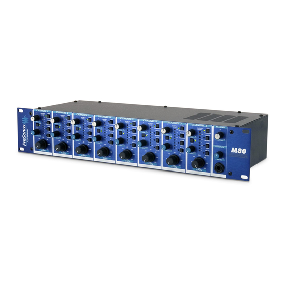
B A S I C L A Y O U T Notice that the front panel is divided into eight identical Preamplifier sections plus a Master section. These are the eight microphone preamplifier channels of the M80. Preamp channels contain: Pan Control... -
Page 10: Preamplifier Section
The effect of manipulating the harmonic distortion is of increasing or decreasing the apparent “warmth” of the signal. This capability is due to a new transformer that PreSonus is proud to debut in the M80. Experiment with IDSS and see what type of sounds you can get from your present microphone selection. -
Page 11: Master Channel
-20 dB Pad provides -20 decibels of attenuation with the push of a button. feature for rapidly reducing the level coming into the M80 and thus preventing the input signal from over- modulating (distorting) the input. This may occur due to high output level from a microphone or line device. - Page 12 B A S I C L A Y O U T Input Jack of the M80 features a Neutrik Combo connector. This connector accepts either a male XLR for microphones or high impedance instruments via the ¼ inch portion of the connector. When an instrument cable is inserted into the ¼...
- Page 13 Stereo Mix Bus. The Aux Inputs can be used to introduce a stereo single such as the output of a stereo tape machine to the Stereo Mix Bus of the M80. The various input signals of the individual channels of the M80 can then be mixed with the introduced stereo signal by using the PAN controls located on the individual channels.
-
Page 14: Power Supply
2.7 Power Supply Power Jack on your M80 Power Supply accepts a standard IEC cord like those found on most computers and professional recorders. You can be assured of clean power and rugged construction that will last a long time! -
Page 15: Dynamic Microphones
3.4 Inserting Compressors, EQ’s, etc. Each channel of the M80 features a send jack and a return jack. This feature allows the use of external processors such as compression and equalization devices. Simply connect the send jack, balanced or unbalanced to the input of the external processor. - Page 16 This provides an opportunity to connect multiple M80’s together thus creating more inputs for the stereo mix bus. Connect the balanced bus outputs of one M80 to the Aux inputs of the next M80. The M80 that is the last in the chain is the master output device. Previous mixes can be controlled similar to sub-...
-
Page 17: Technical
4 TECHNICAL M80 Technical Specifications: Number of Channels Dynamic Range Noise Floor @ Bus Noise Floor @ Main Output Noise Floor @ Channel Output, +24dB Gain Headroom Frequency Response +/- 0.5dB Crosstalk Channel Gain, Microphone Input THD + Noise, (no idss) - Page 18 CONTROLS & CONNECTIONS...